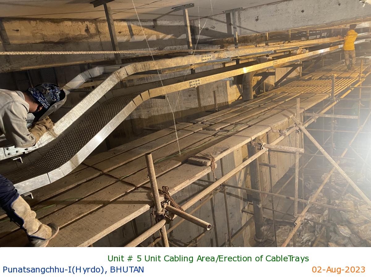
Unit # 5 Unit Cabling Area/Erection of CableTrays
|
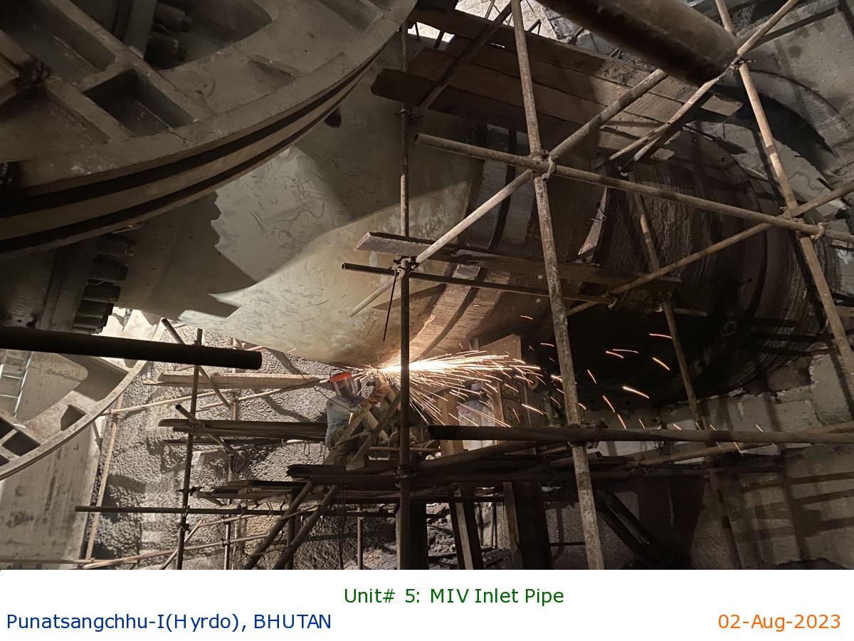
Unit# 5: MIV Inlet Pipe
|
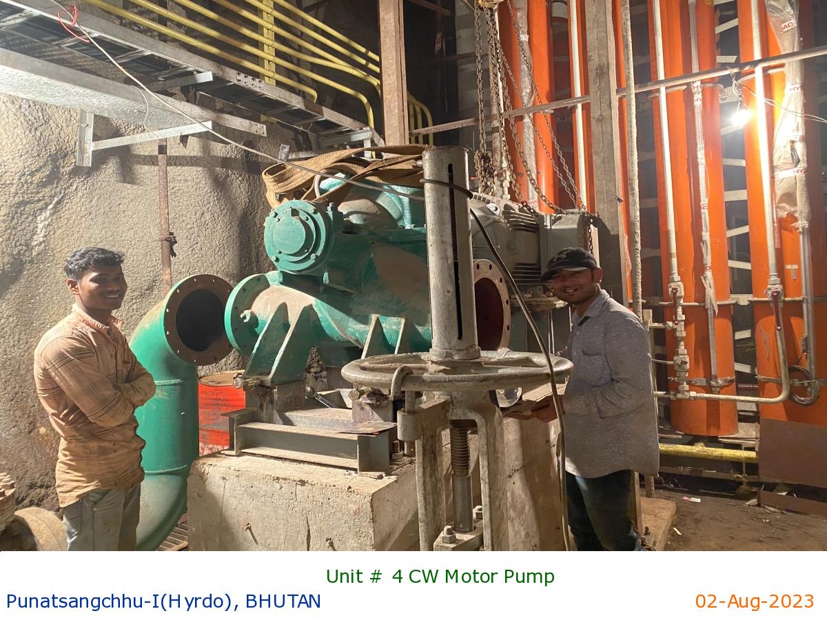
Unit # 4 CW Motor Pump
|
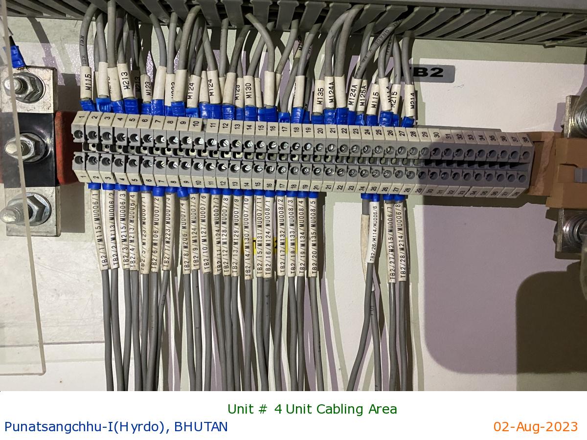
Unit # 4 Unit Cabling Area
|
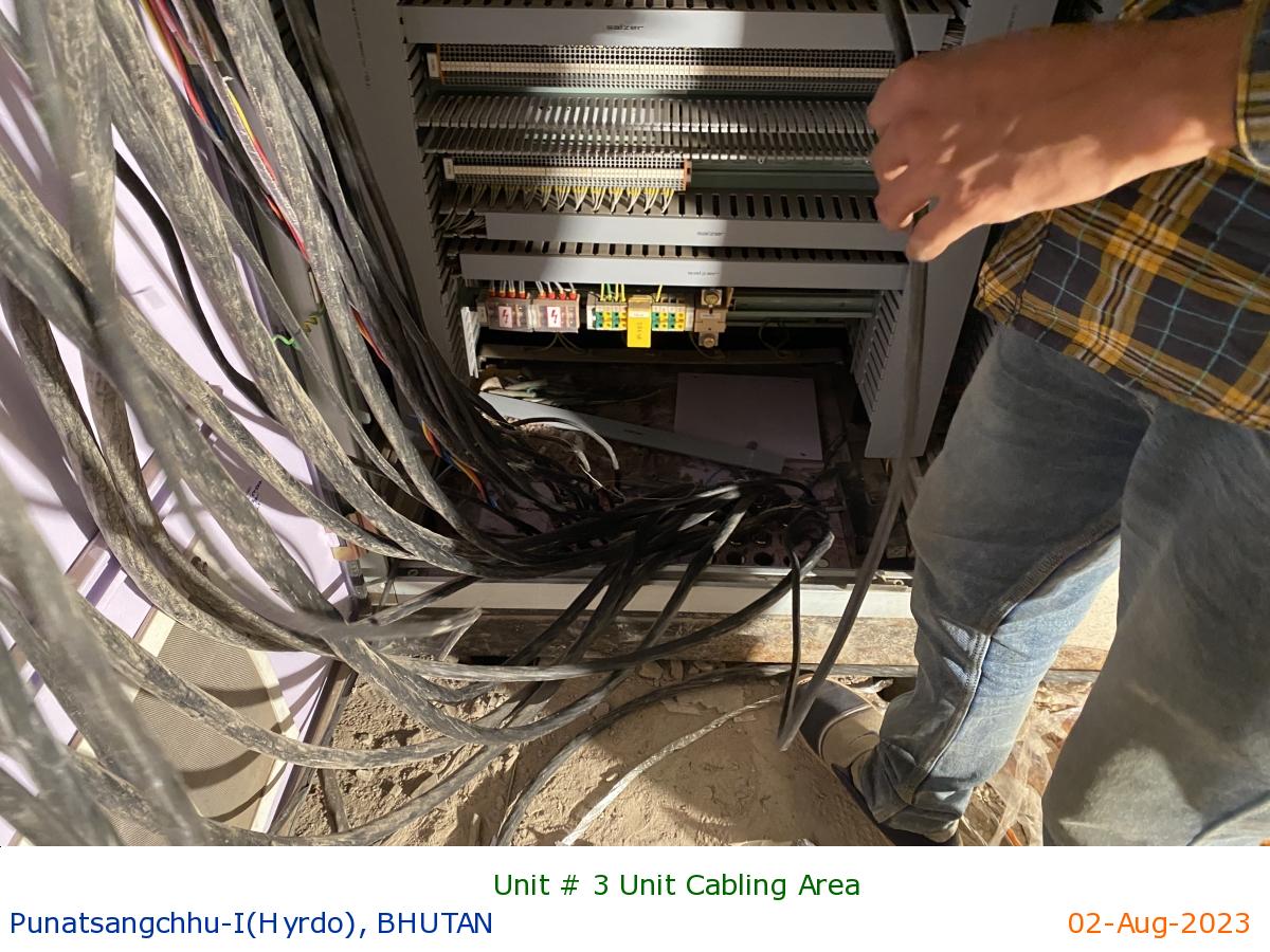
Unit # 3 Unit Cabling Area
|
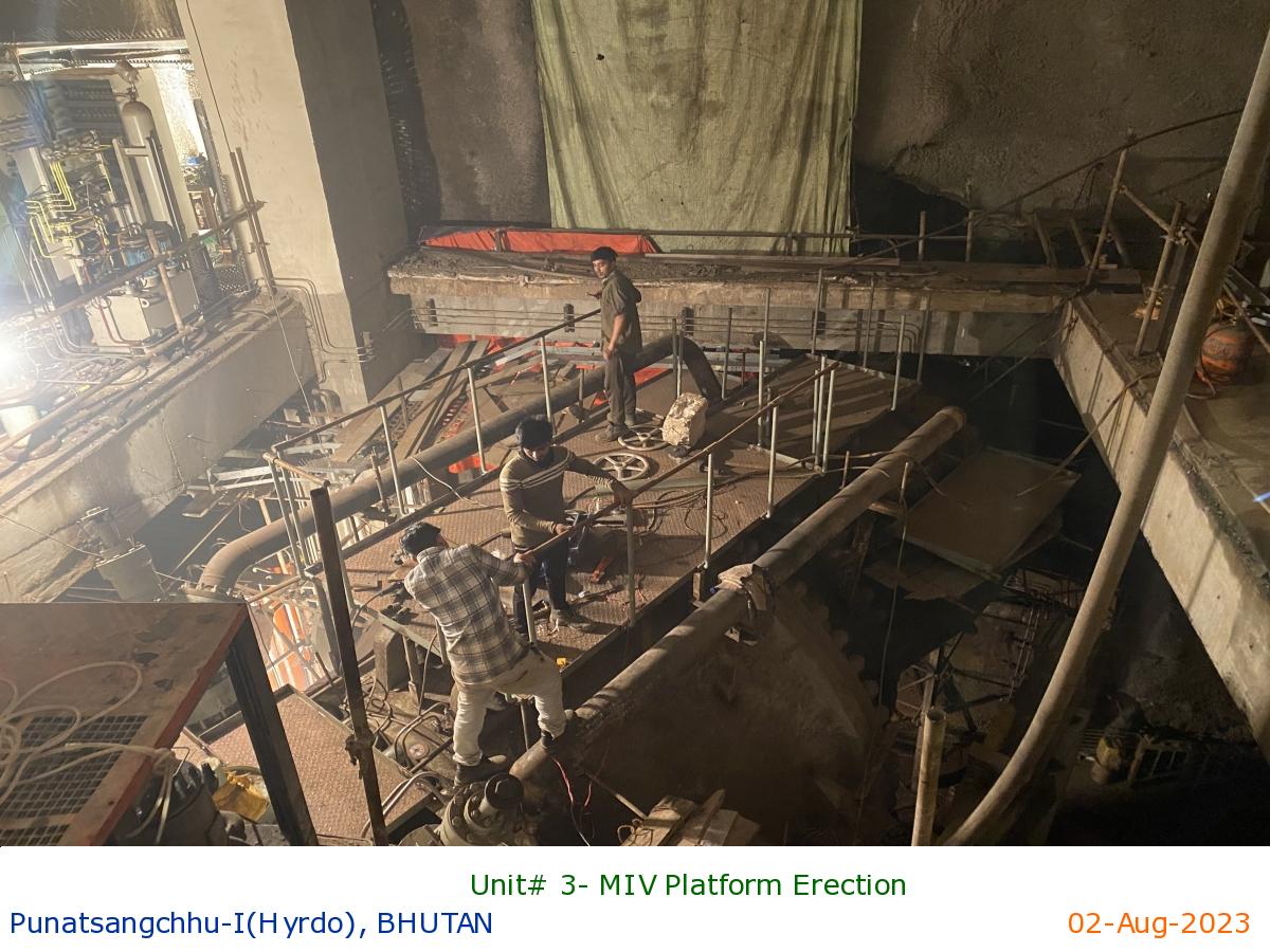
Unit# 3- MIV Platform Erection
|
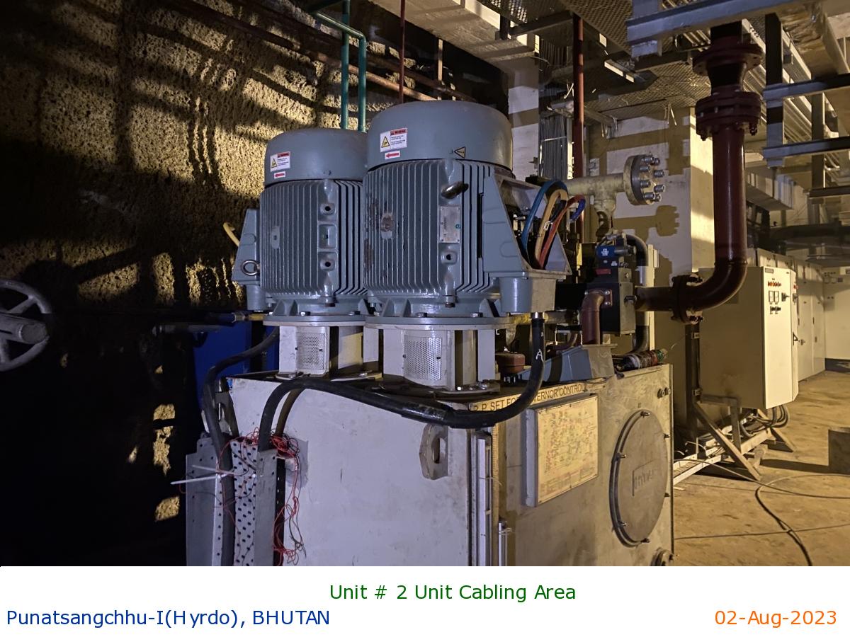
Unit # 2 Unit Cabling Area
|
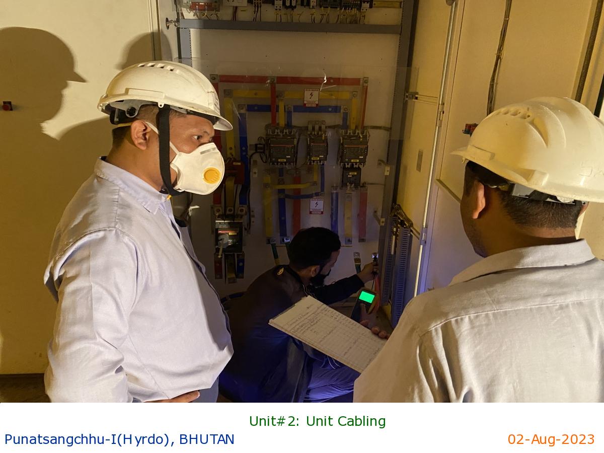
Unit#2: Unit Cabling
|
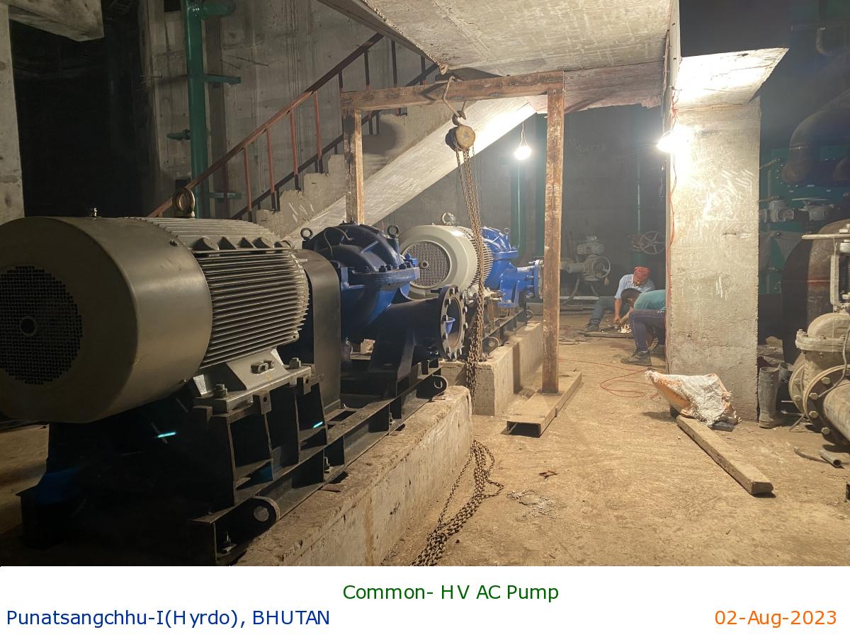
Common- HV AC Pump
|
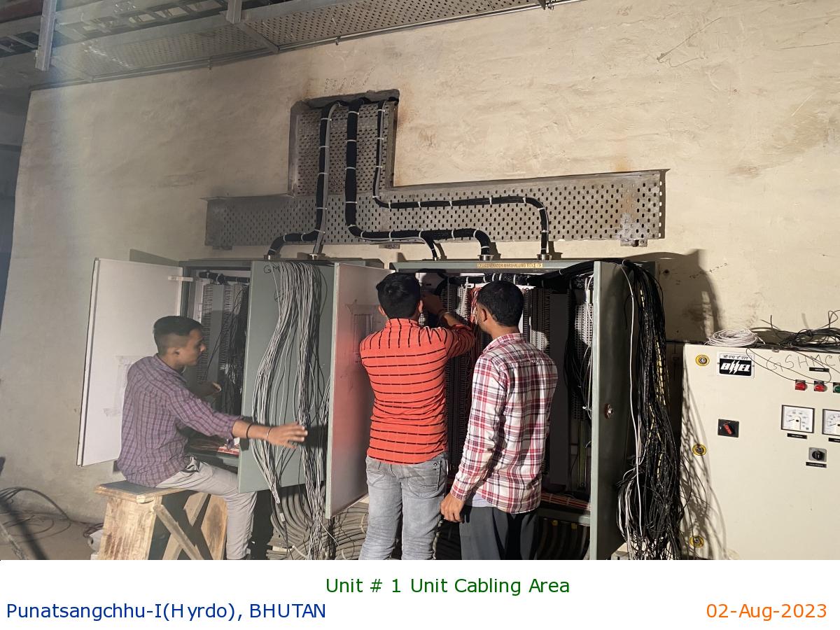
Unit # 1 Unit Cabling Area
|
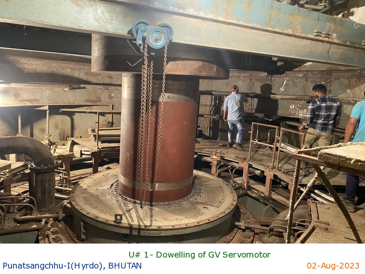
U# 1- Dowelling of GV Servomotor
|
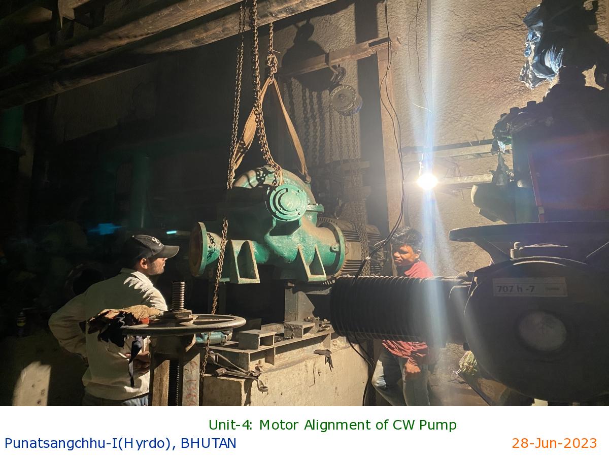
Unit-4: Motor Alignment of CW Pump
|
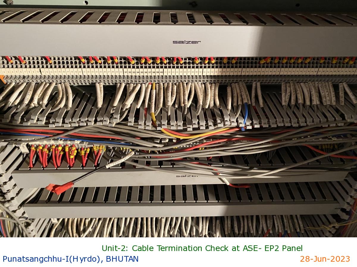
Unit-2: Cable Termination Check at ASE- EP2 Panel
|
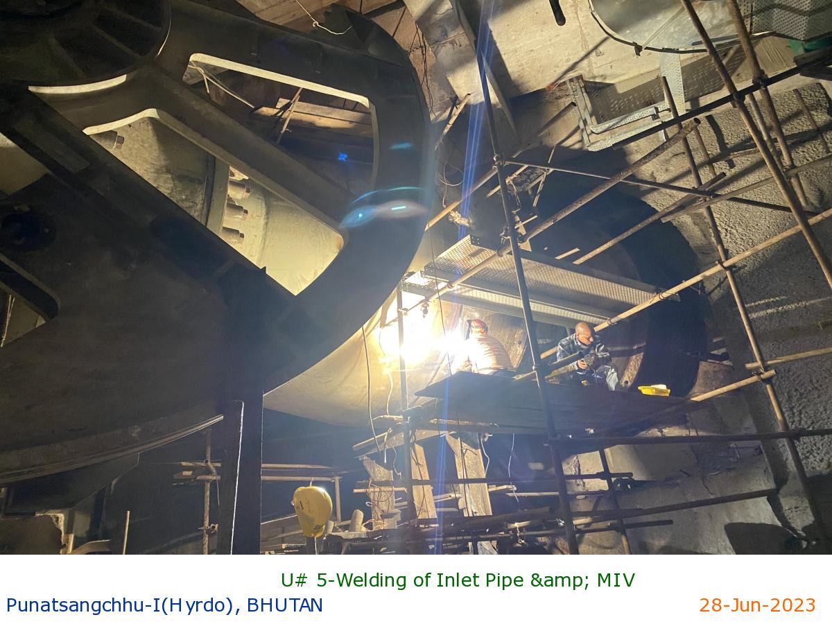
U# 5-Welding of Inlet Pipe & MIV
|
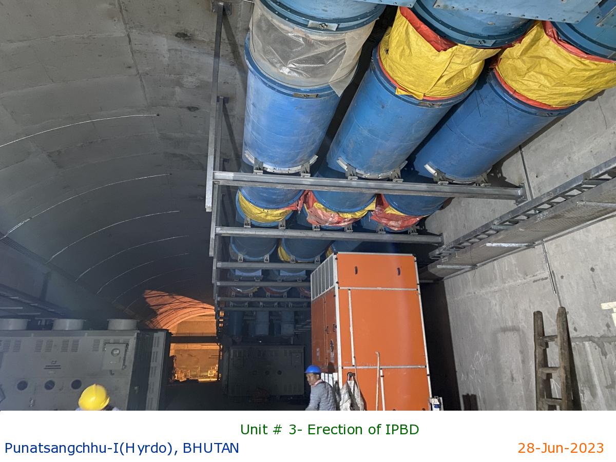
Unit # 3- Erection of IPBD
|
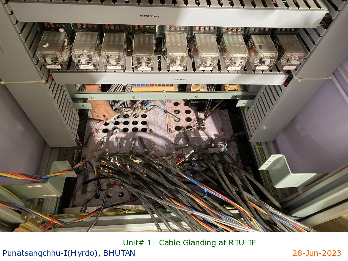
Unit# 1- Cable Glanding at RTU-TF
|
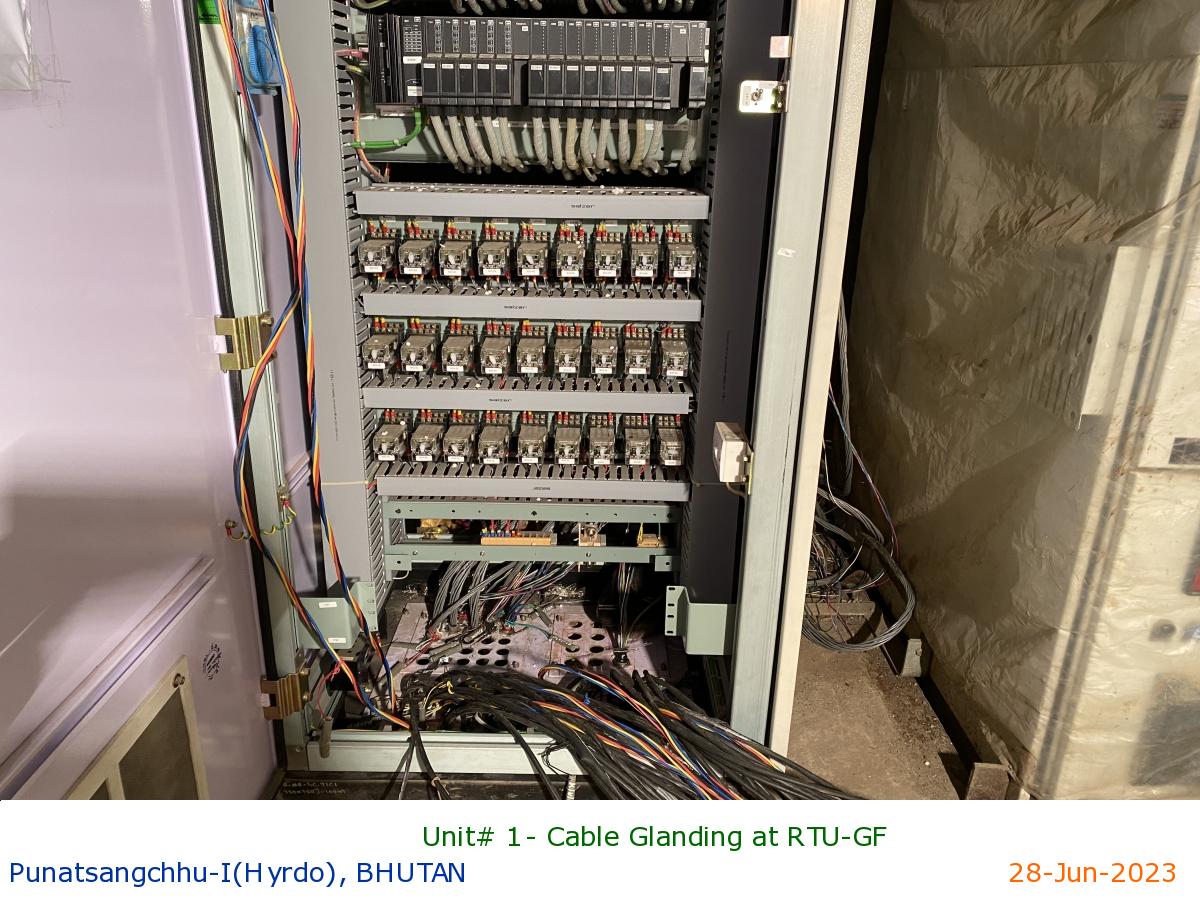
Unit# 1- Cable Glanding at RTU-GF
|
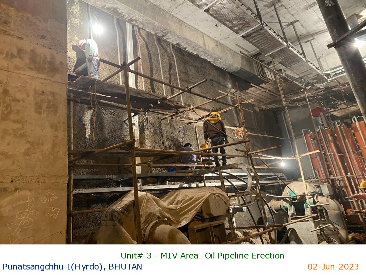
Unit# 3 - MIV Area -Oil Pipeline Erection
|
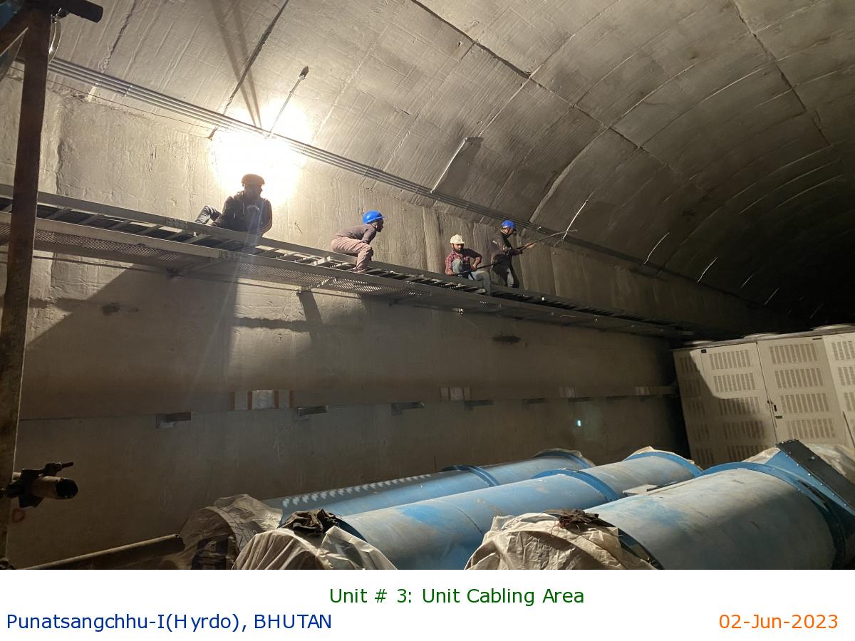
Unit # 3: Unit Cabling Area
|
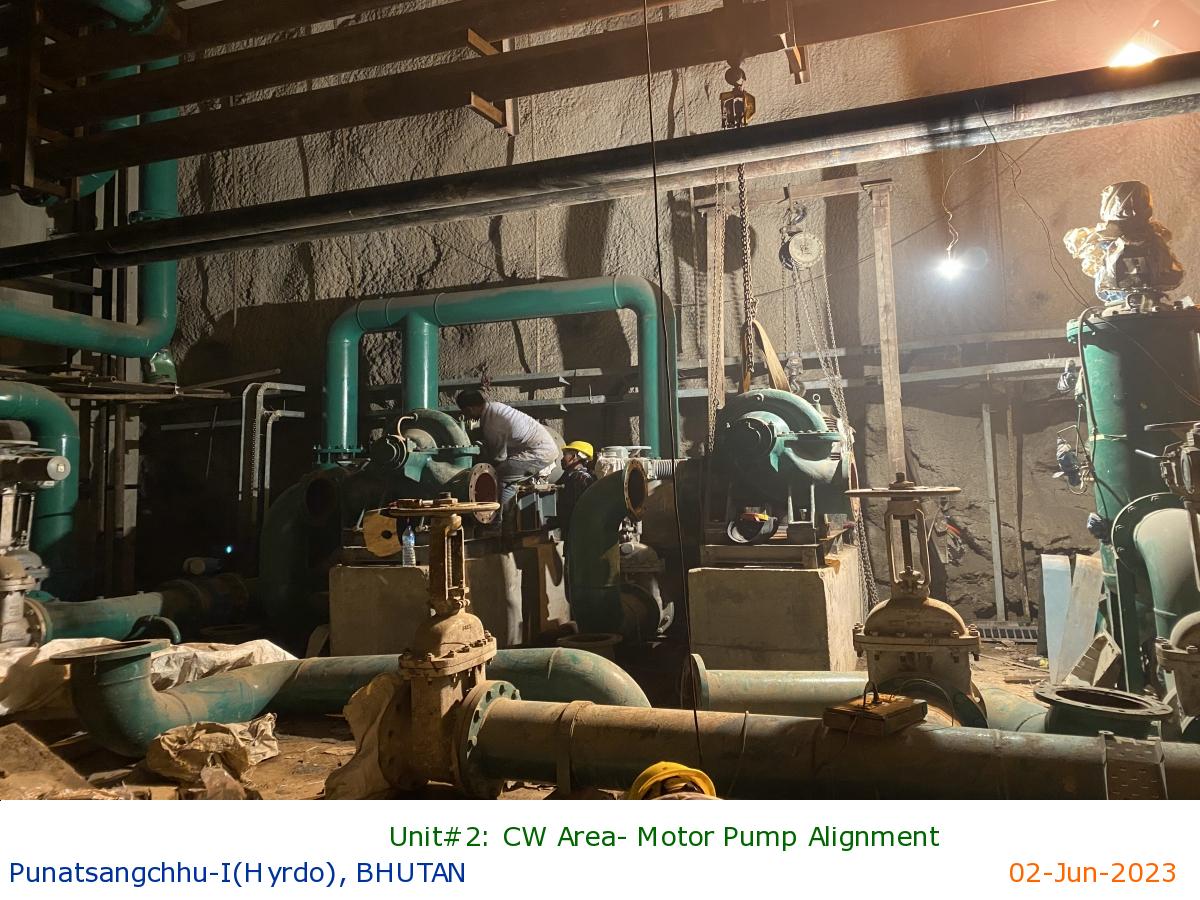
Unit#2: CW Area- Motor Pump Alignment
|
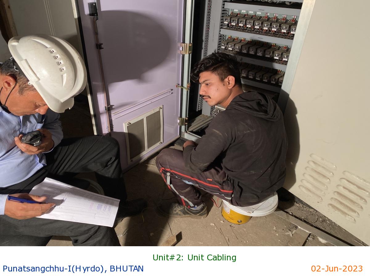
Unit#2: Unit Cabling
|
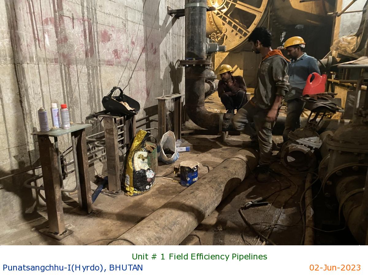
Unit # 1 Field Efficiency Pipelines
|
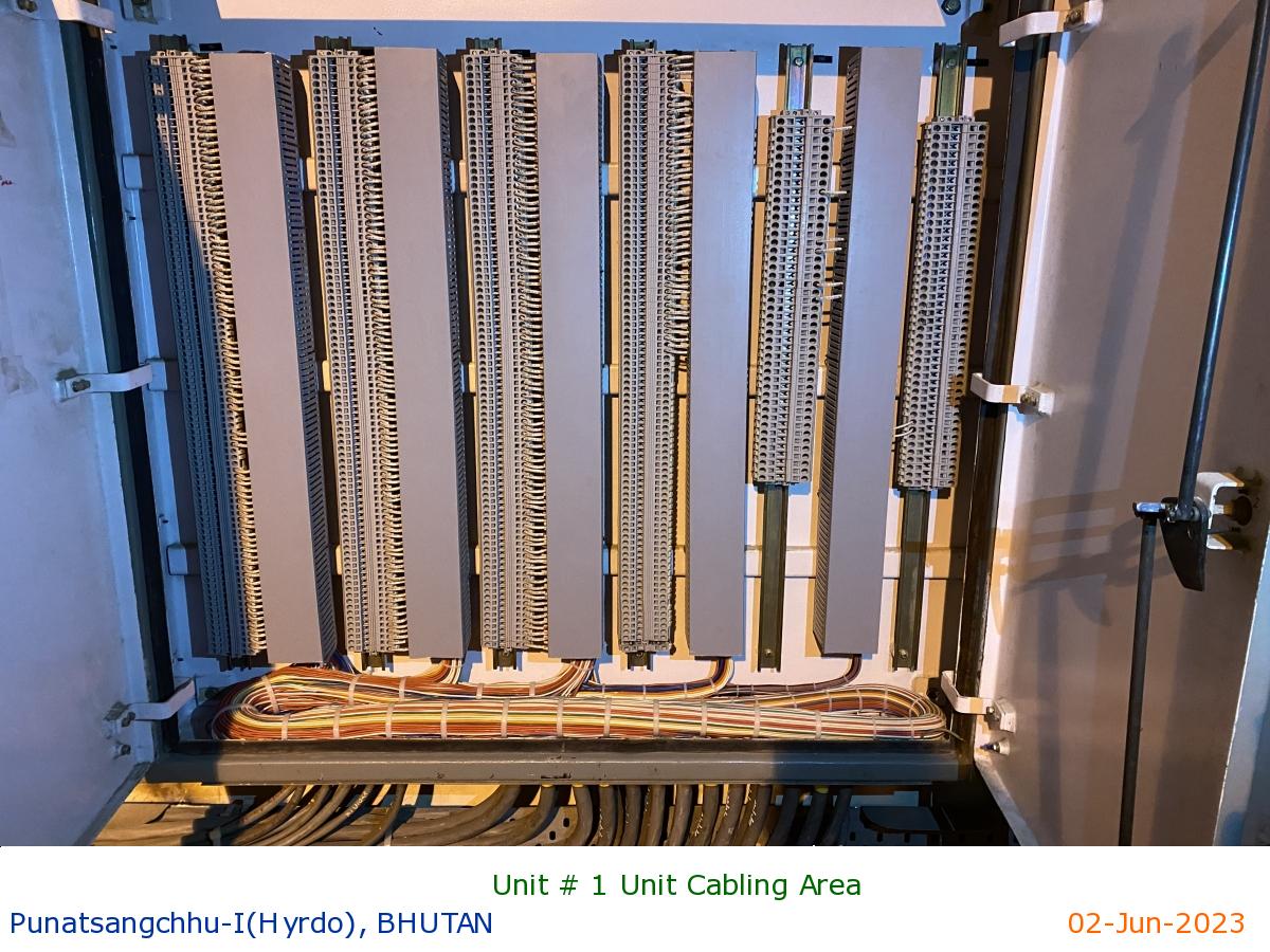
Unit # 1 Unit Cabling Area
|
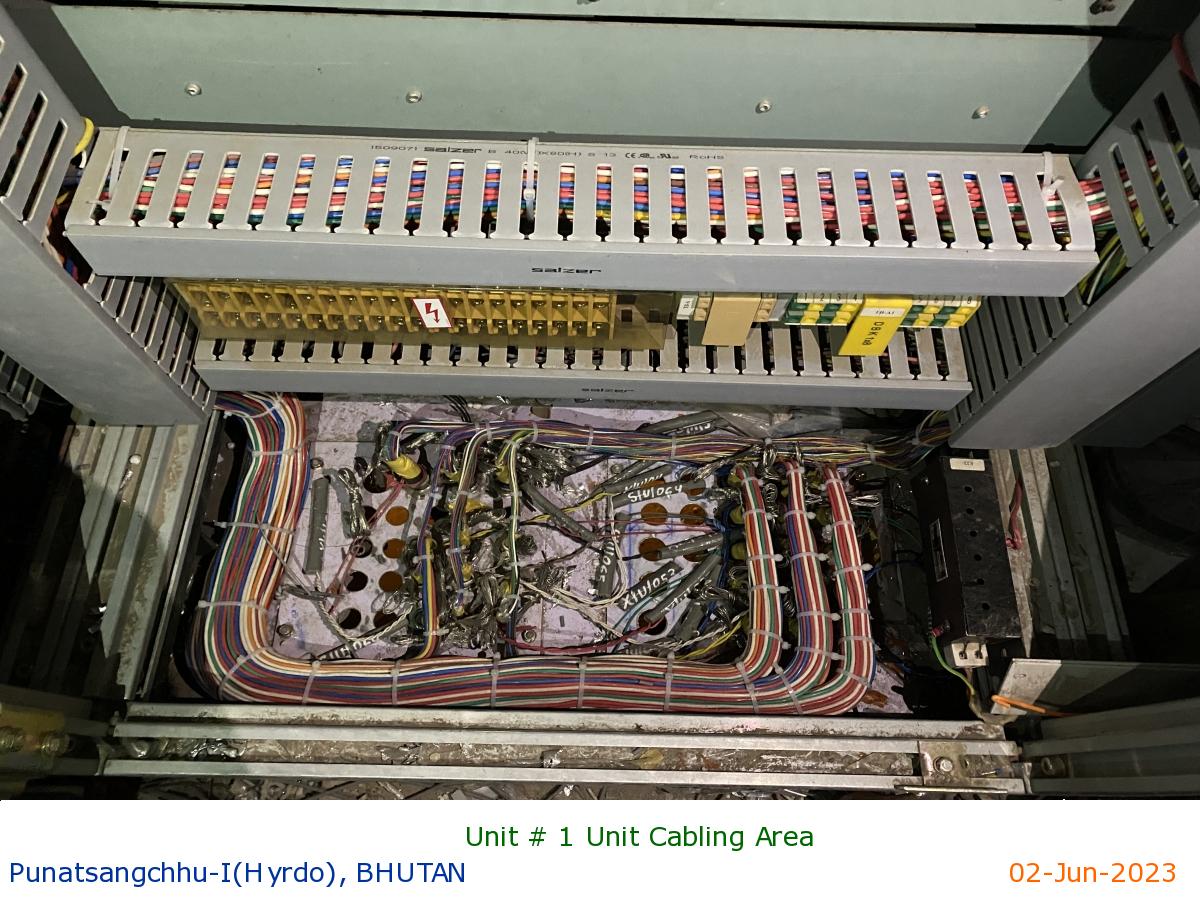
Unit # 1 Unit Cabling Area
|
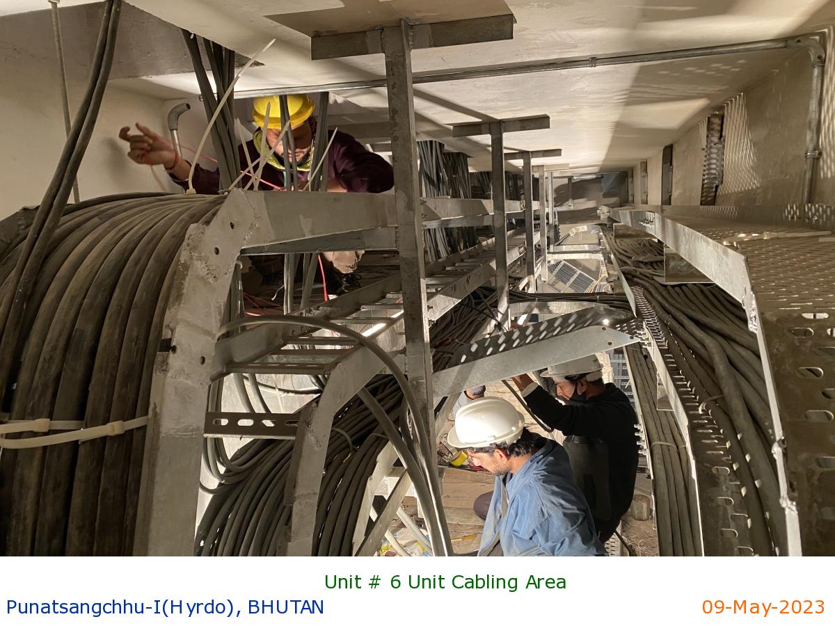
Unit # 6 Unit Cabling Area
|
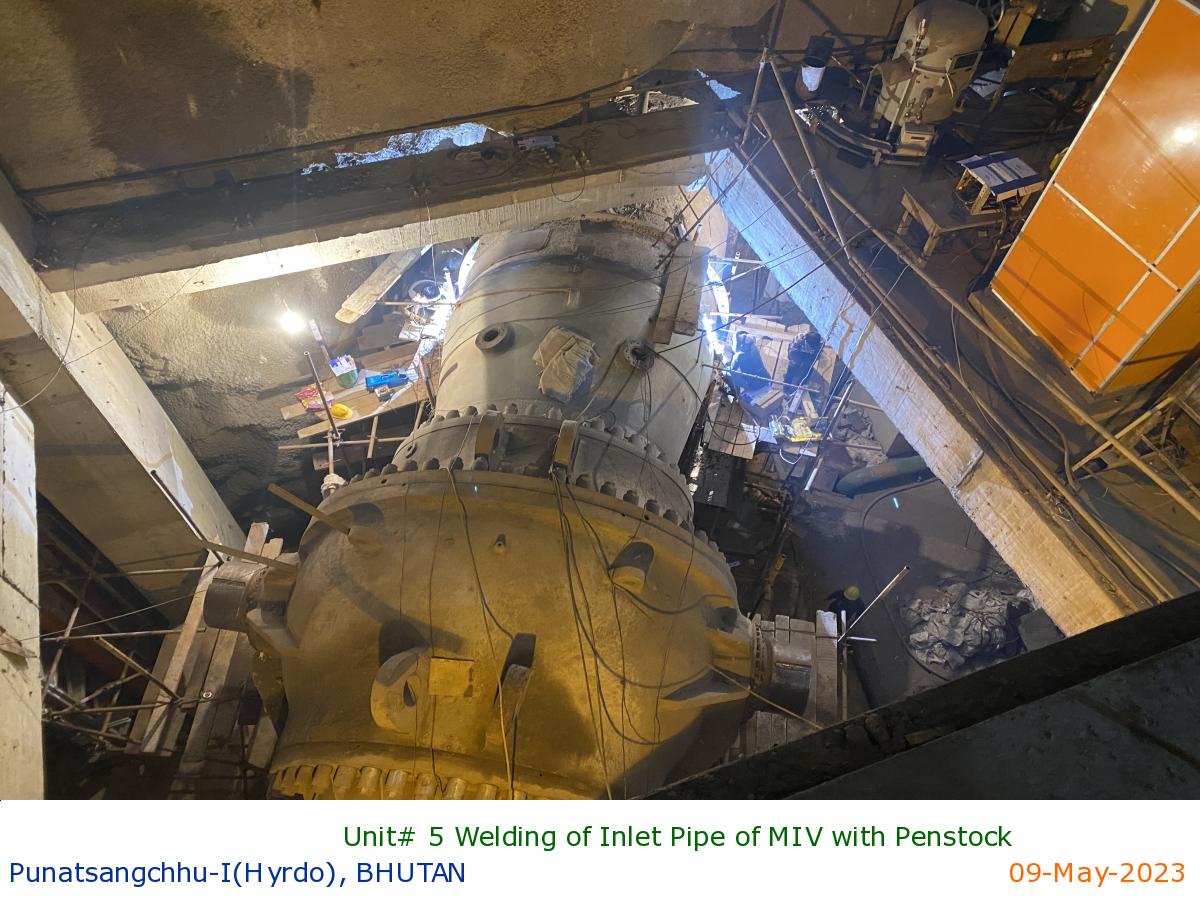
Unit# 5 Welding of Inlet Pipe of MIV with Penstock
|
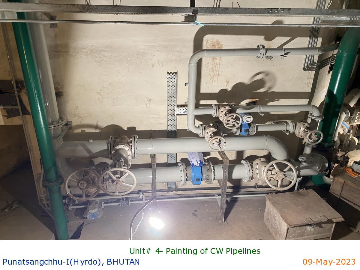
Unit# 4- Painting of CW Pipelines
|
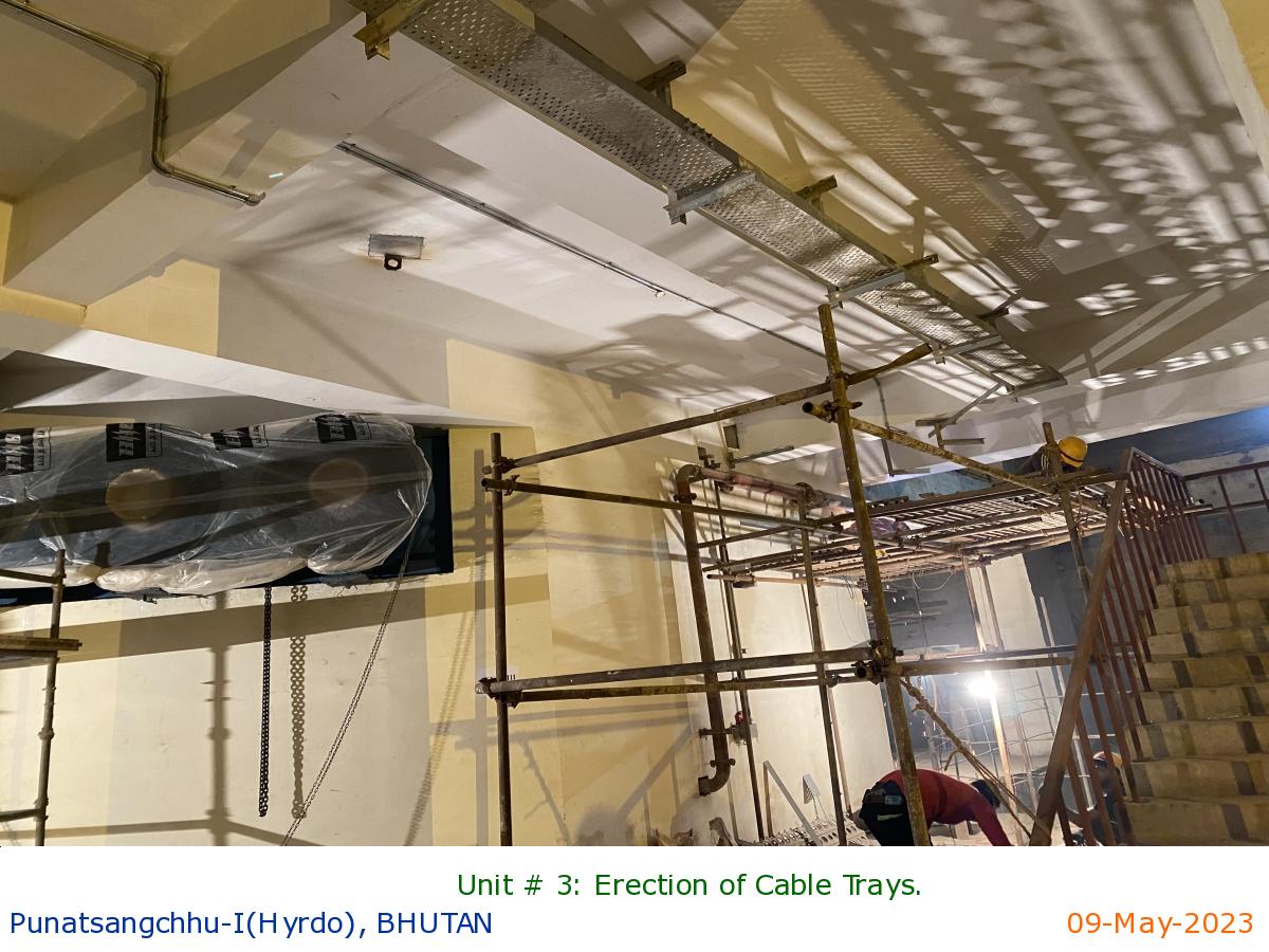
Unit # 3: Erection of Cable Trays.
|
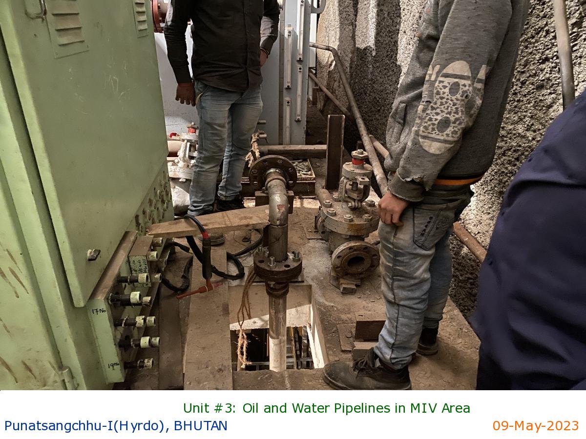
Unit #3: Oil and Water Pipelines in MIV Area
|
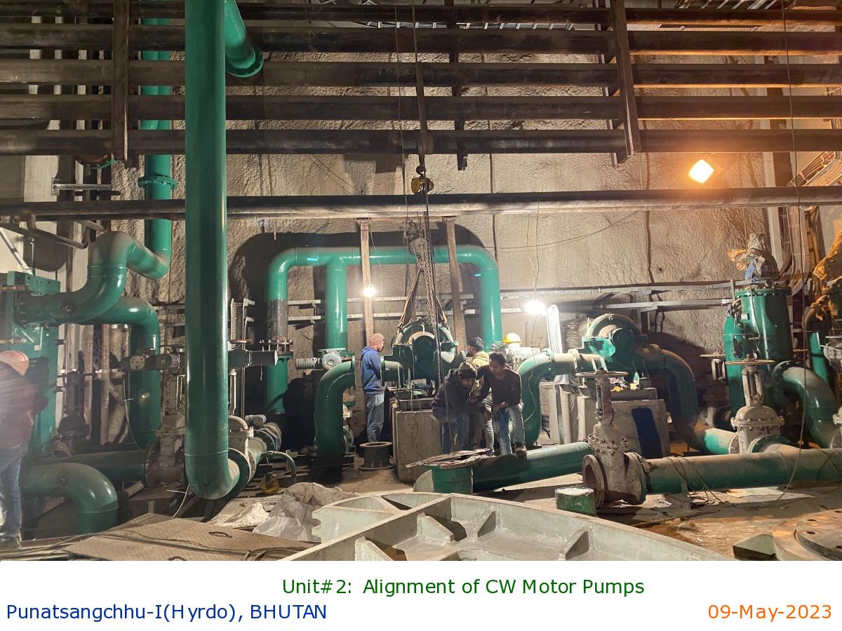
Unit#2: Alignment of CW Motor Pumps
|
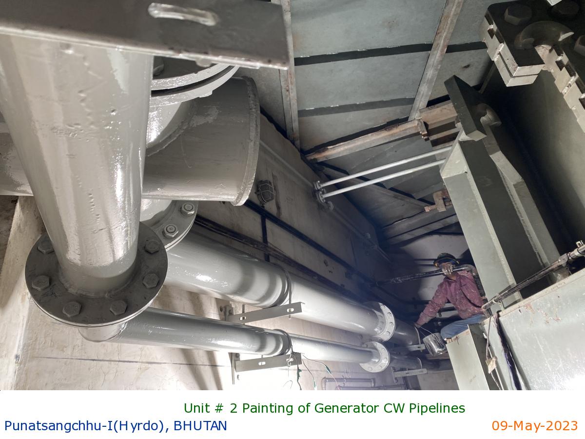
Unit # 2 Painting of Generator CW Pipelines
|
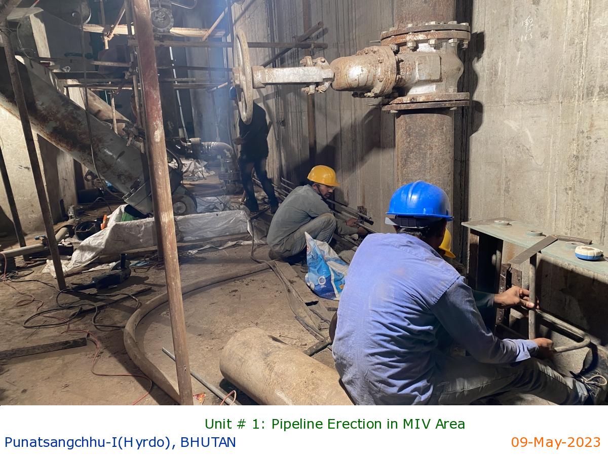
Unit # 1: Pipeline Erection in MIV Area
|
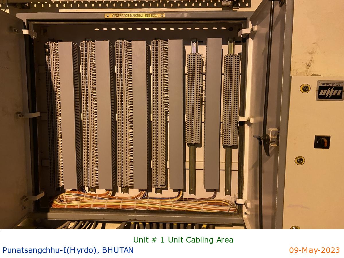
Unit # 1 Unit Cabling Area
|
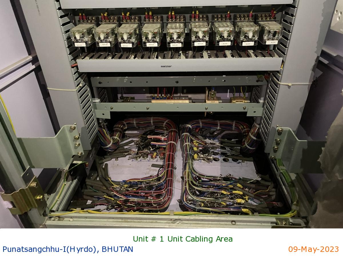
Unit # 1 Unit Cabling Area
|
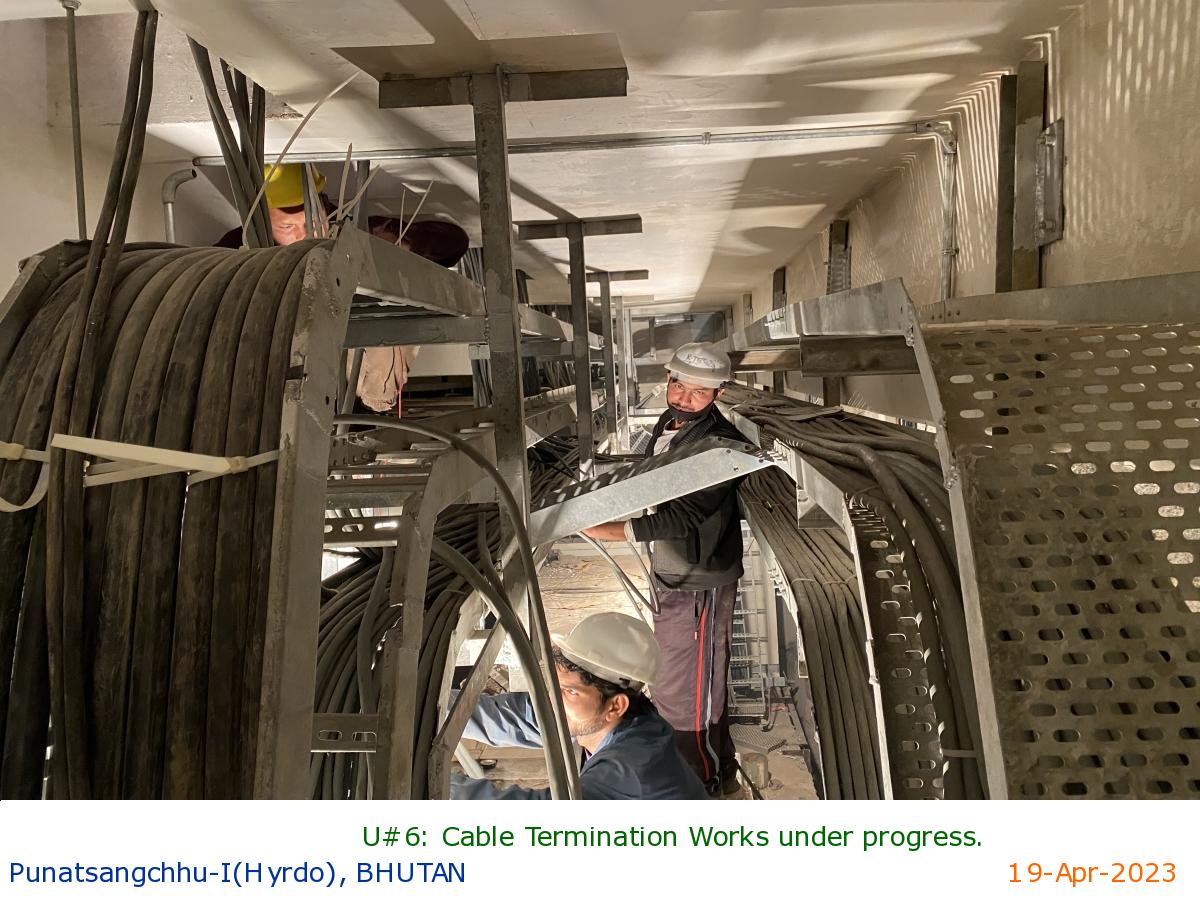
U#6: Cable Termination Works under progress.
|
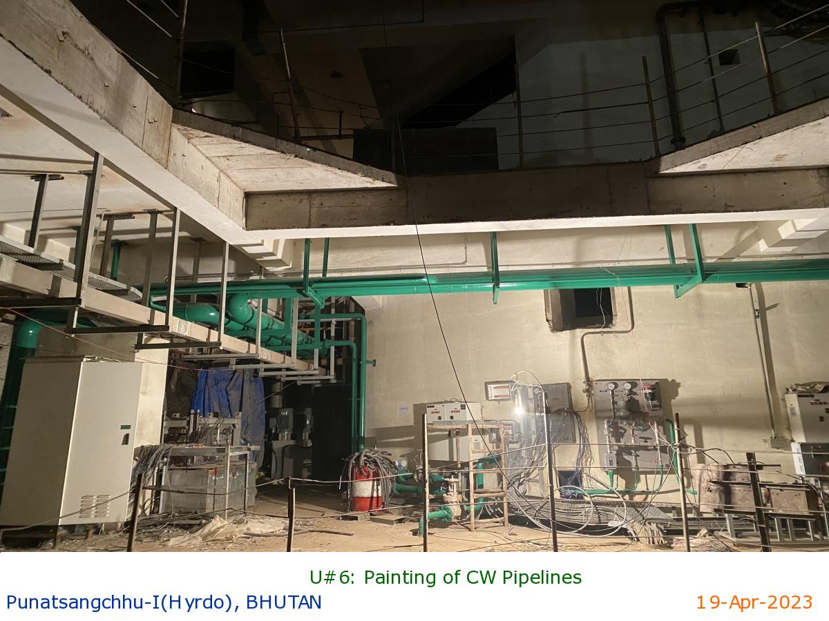
U#6: Painting of CW Pipelines
|
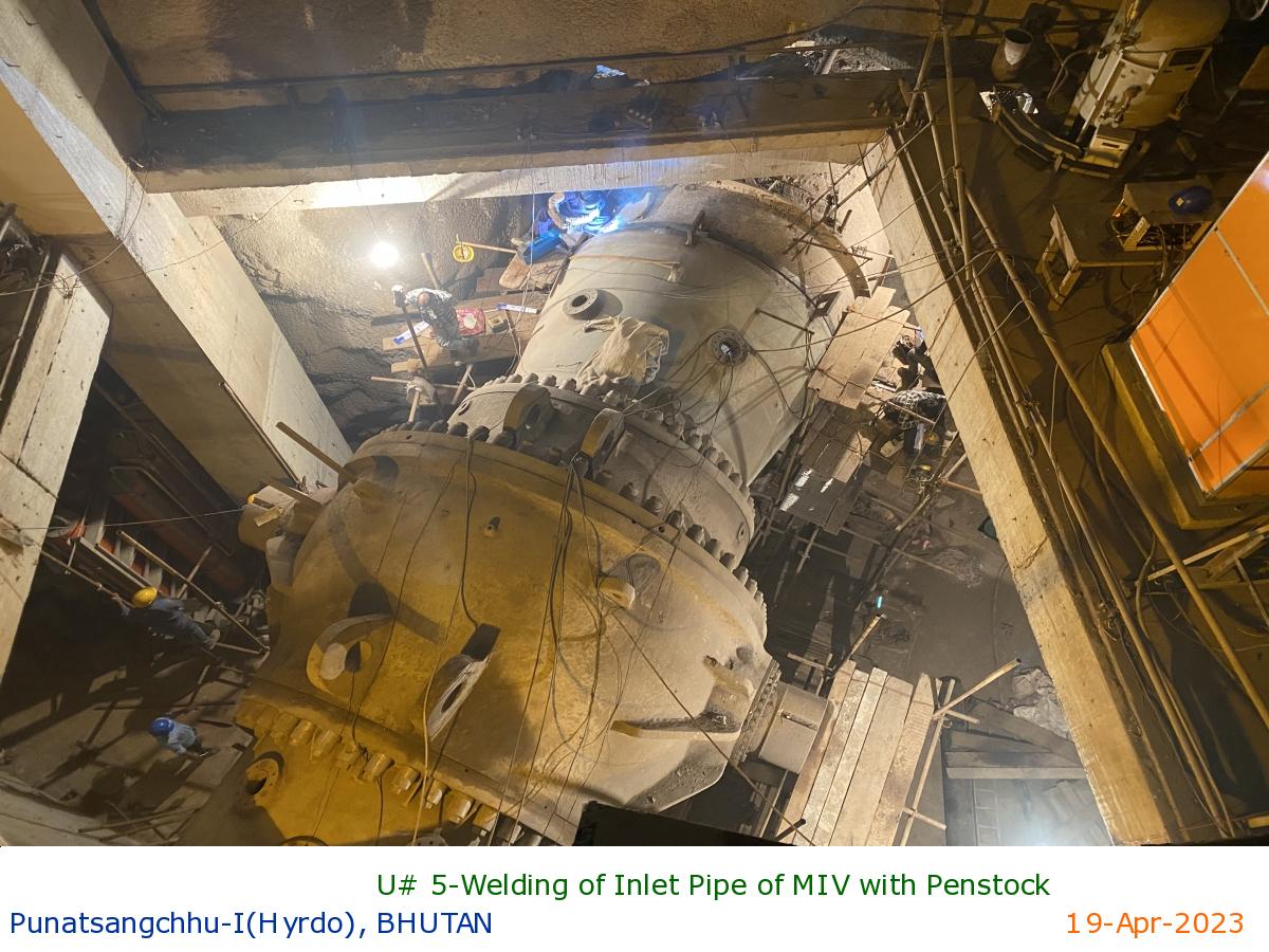
U# 5-Welding of Inlet Pipe of MIV with Penstock
|
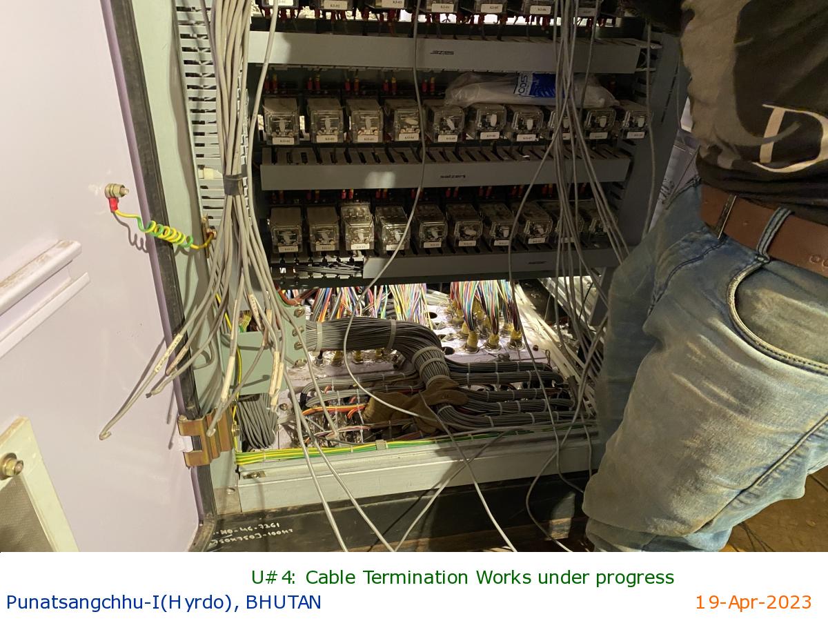
U#4: Cable Termination Works under progress
|
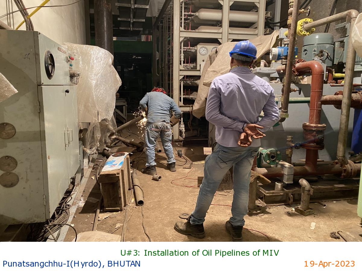
U#3: Installation of Oil Pipelines of MIV
|
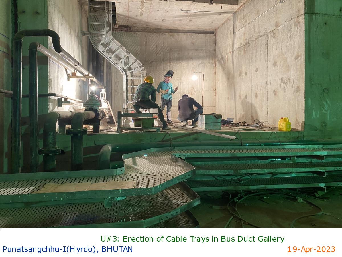
U#3: Erection of Cable Trays in Bus Duct Gallery
|
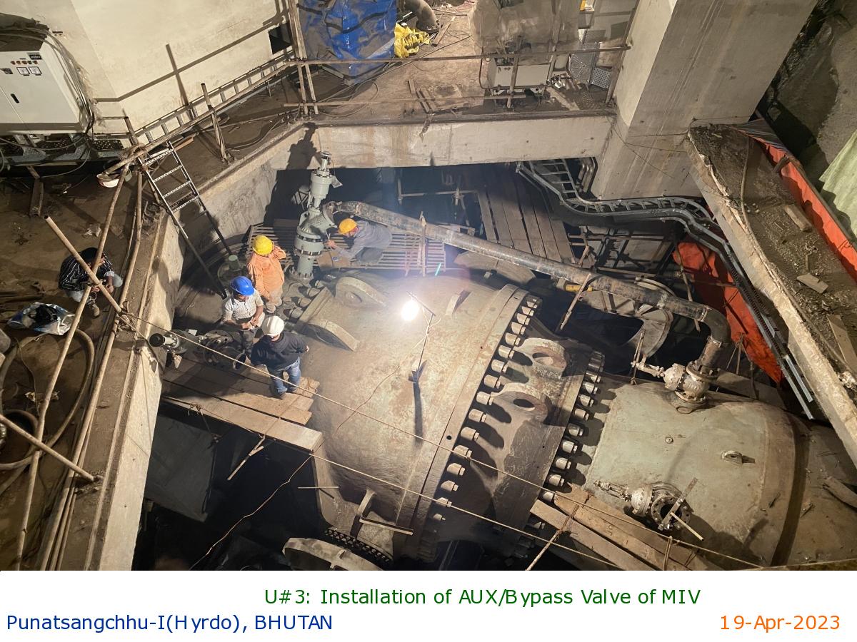
U#3: Installation of AUX/Bypass Valve of MIV
|
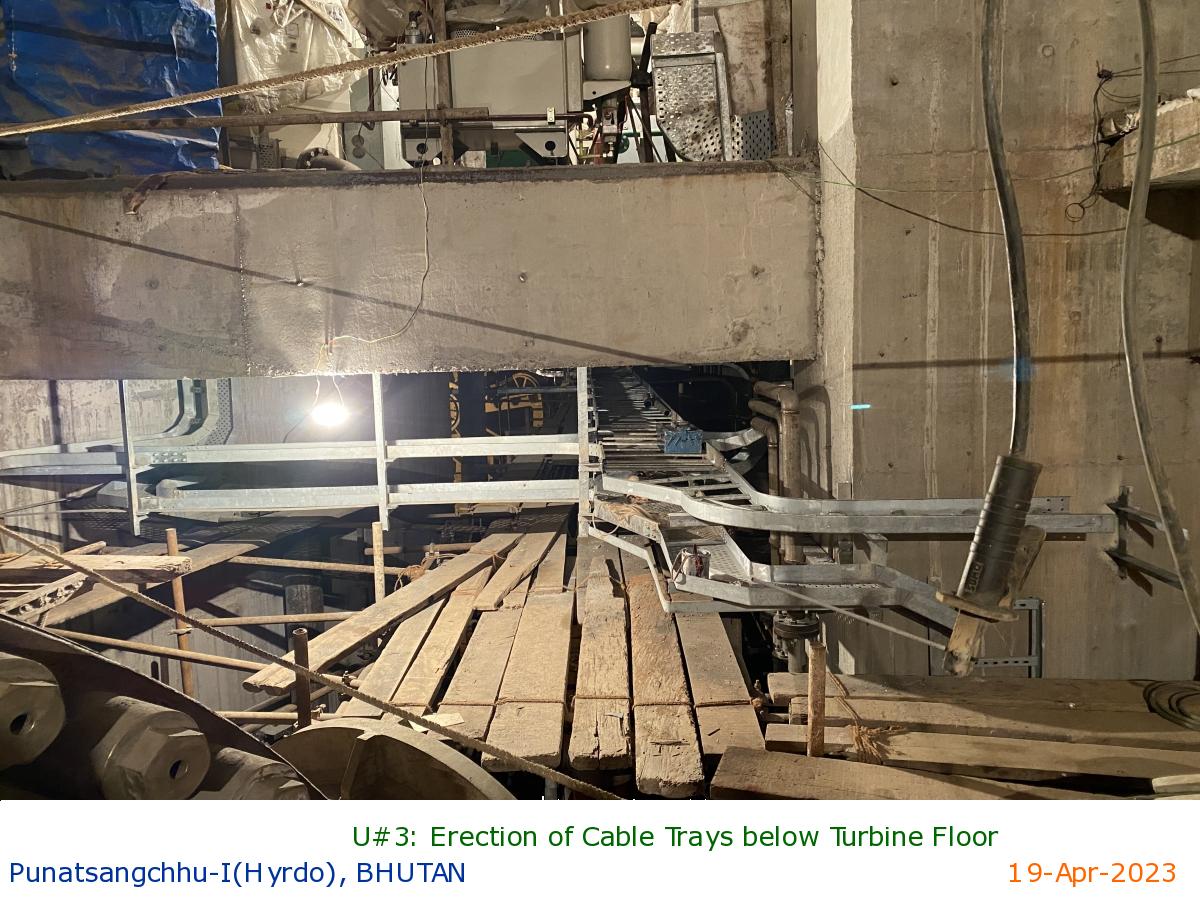
U#3: Erection of Cable Trays below Turbine Floor
|
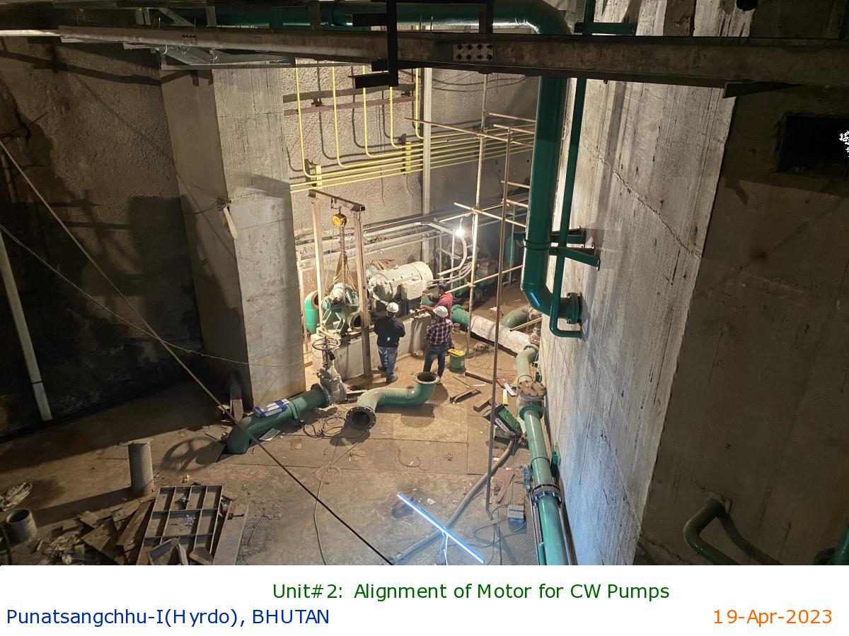
Unit#2: Alignment of Motor for CW Pumps
|
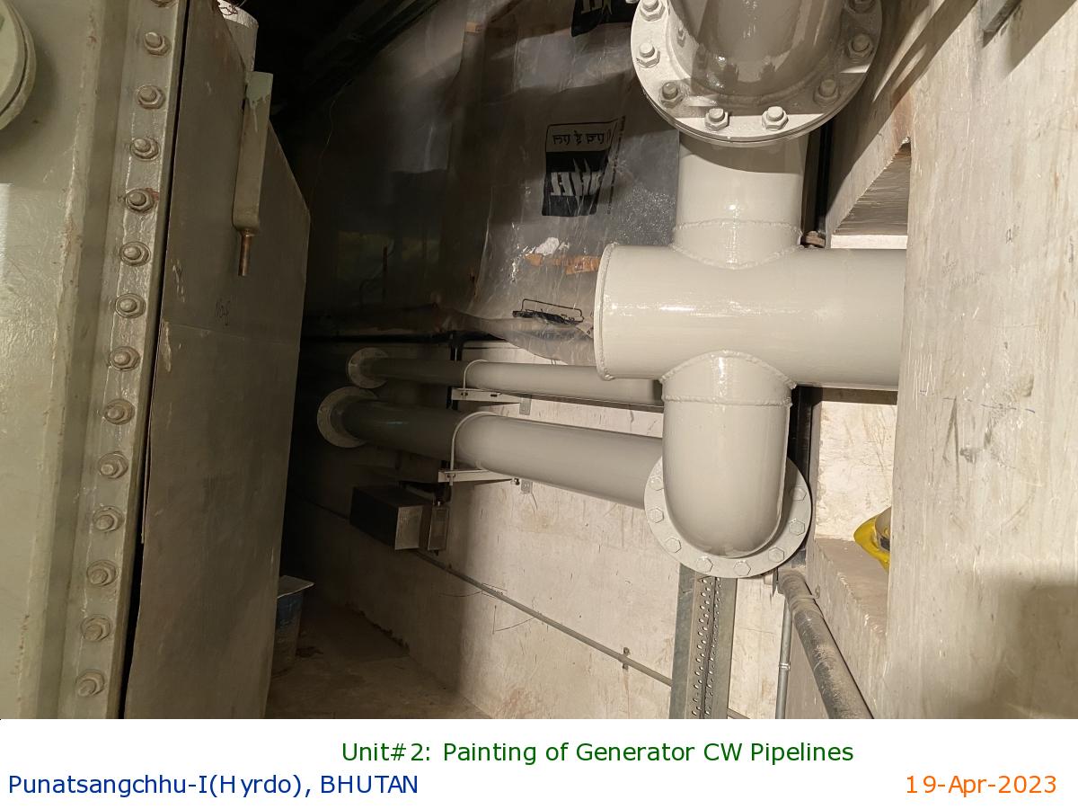
Unit#2: Painting of Generator CW Pipelines
|
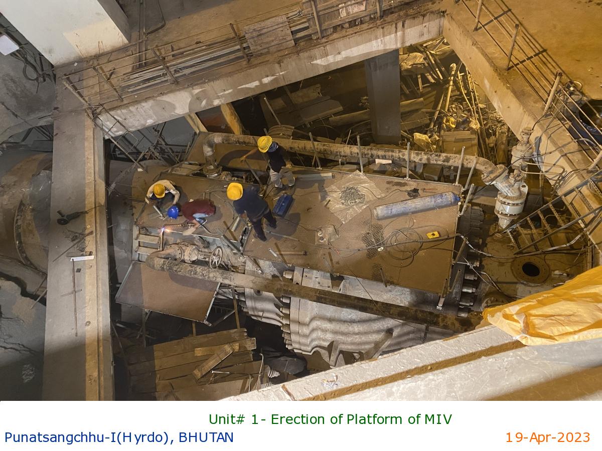
Unit# 1- Erection of Platform of MIV
|
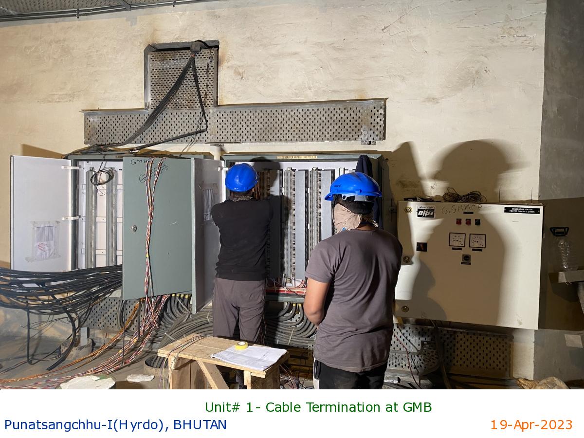
Unit# 1- Cable Termination at GMB
|
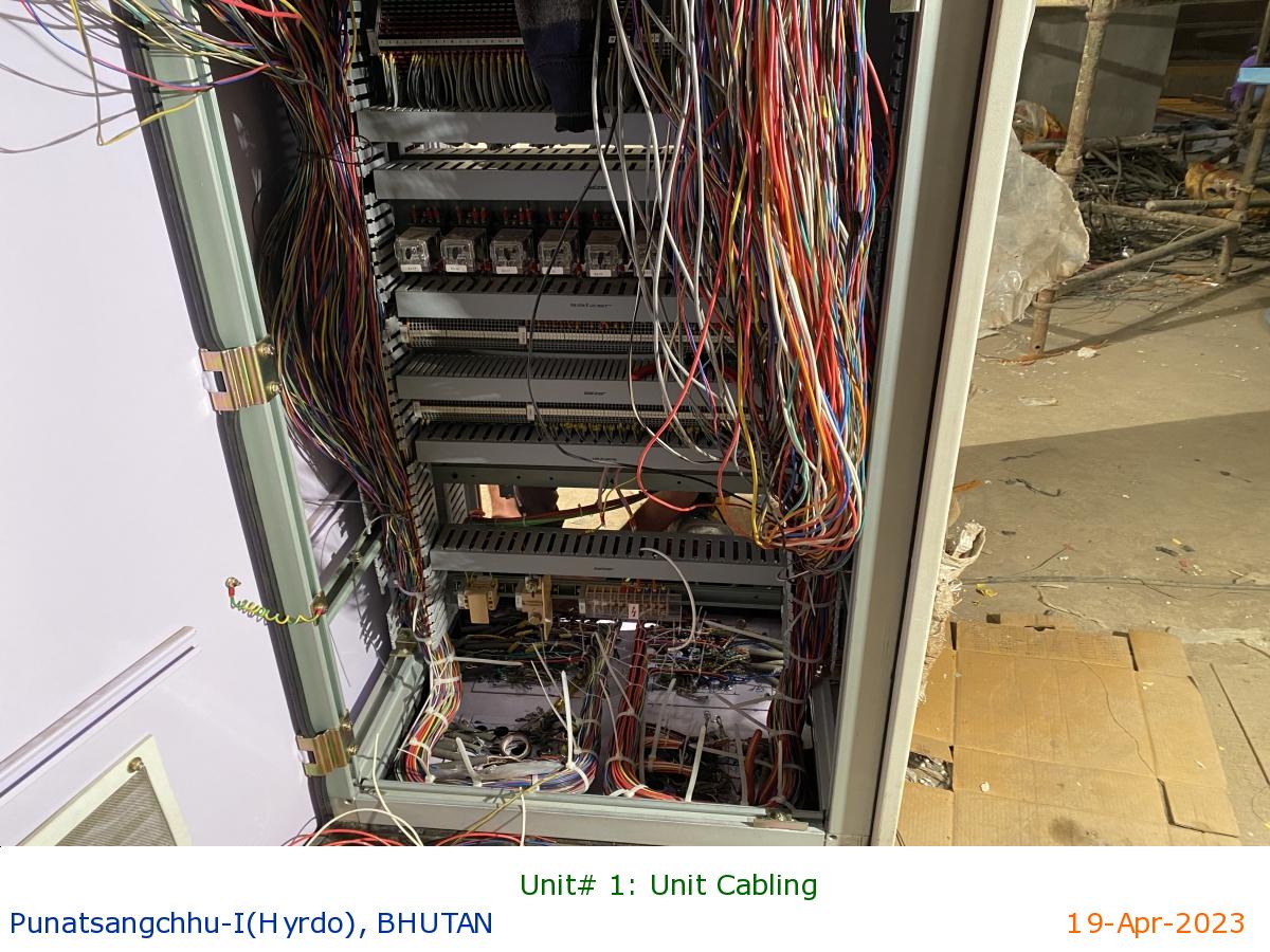
Unit# 1: Unit Cabling
|
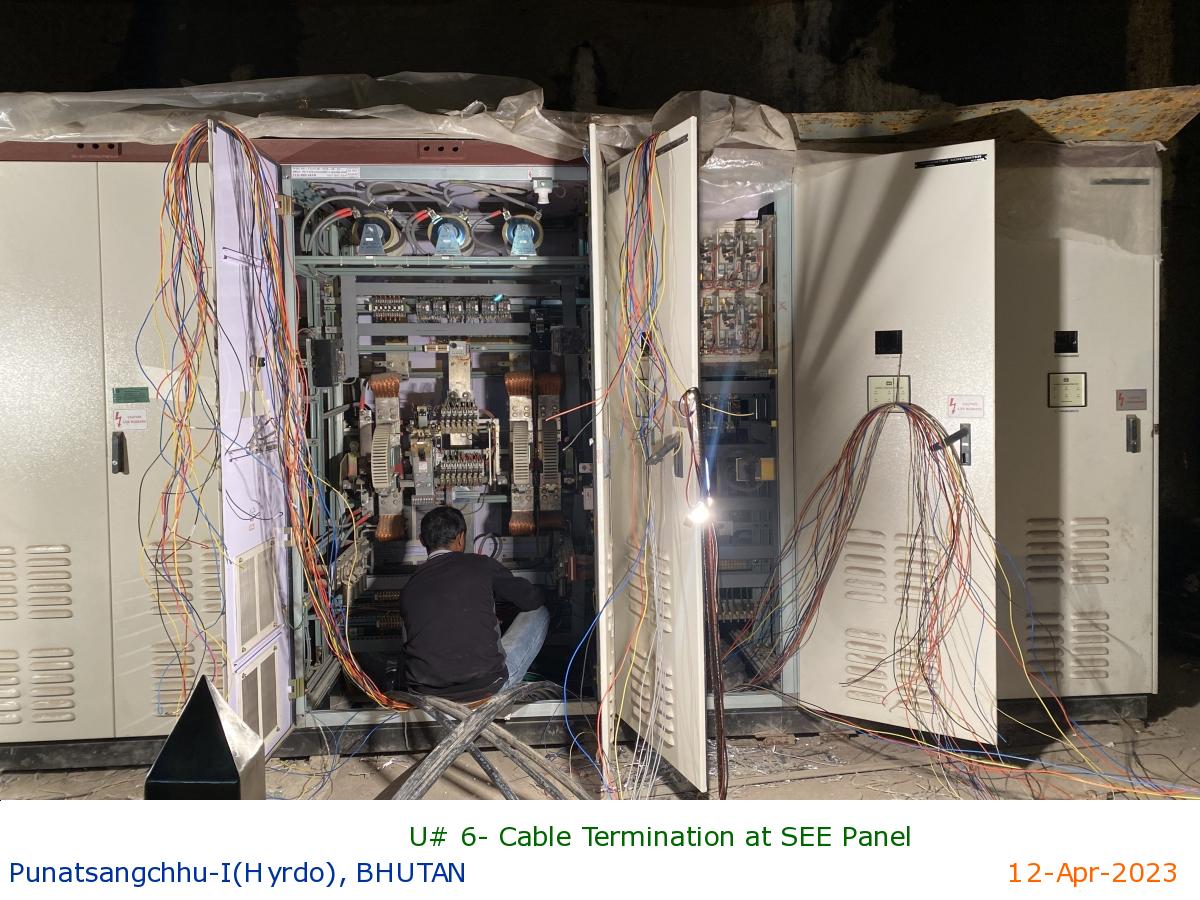
U# 6- Cable Termination at SEE Panel
|
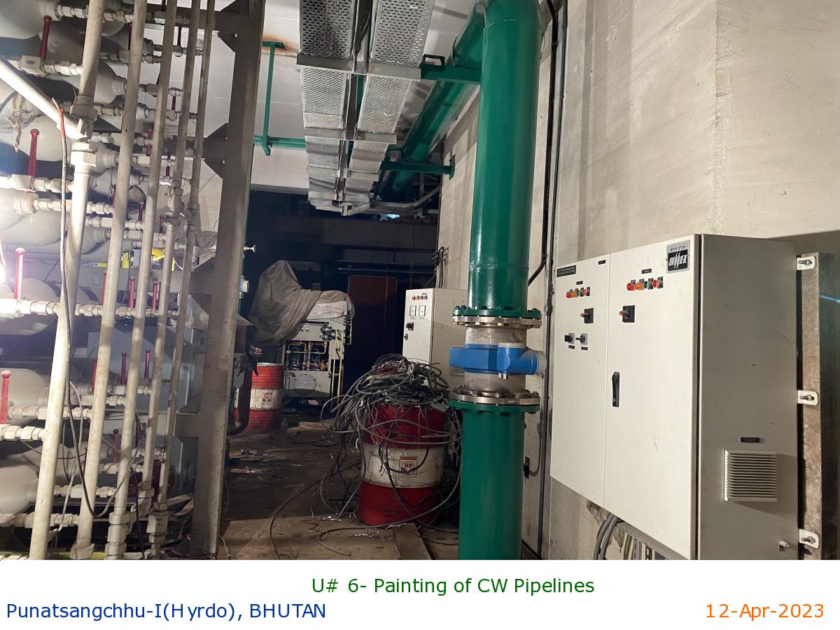
U# 6- Painting of CW Pipelines
|
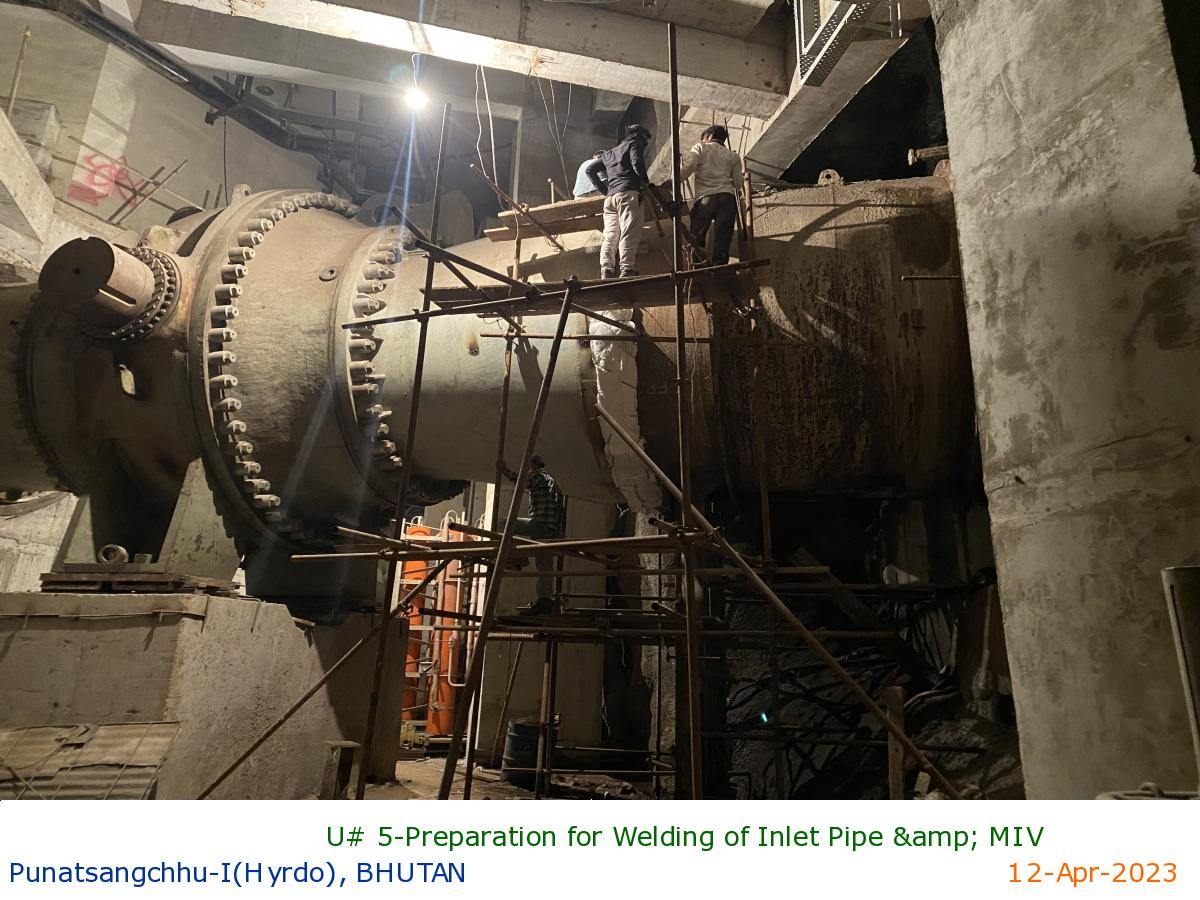
U# 5-Preparation for Welding of Inlet Pipe & MIV
|
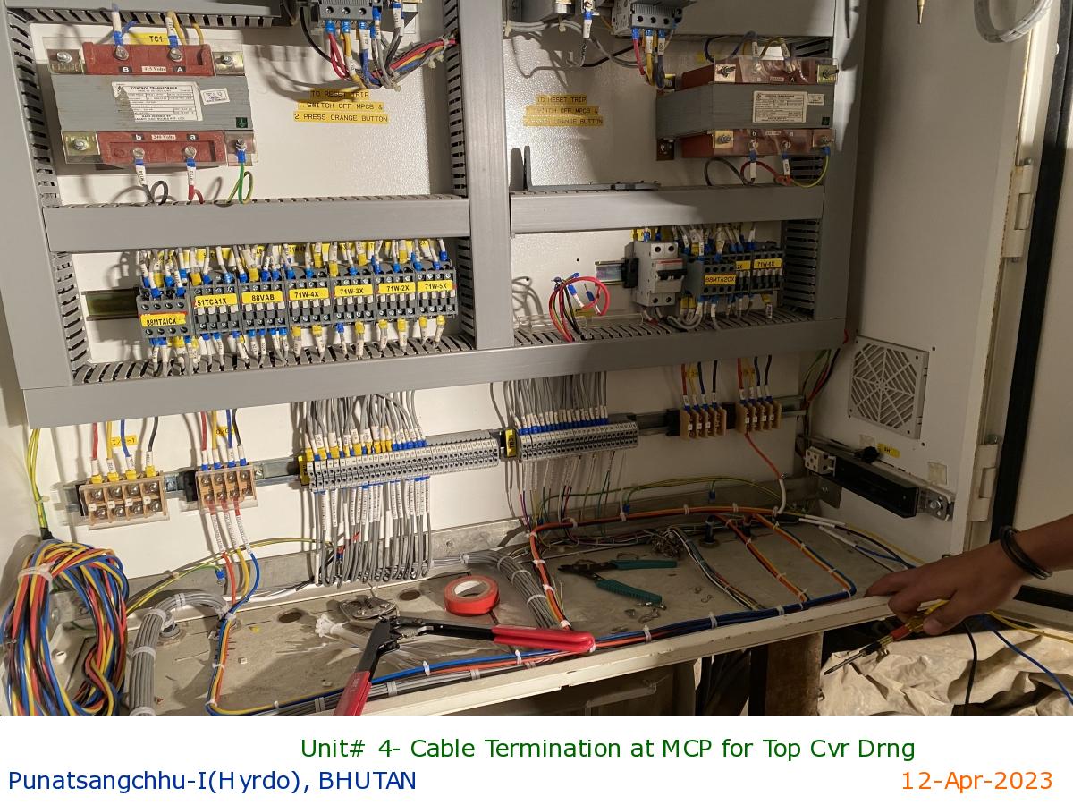
Unit# 4- Cable Termination at MCP for Top Cvr Drng
|
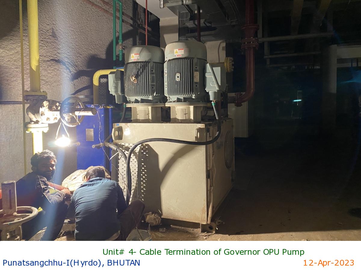
Unit# 4- Cable Termination of Governor OPU Pump
|
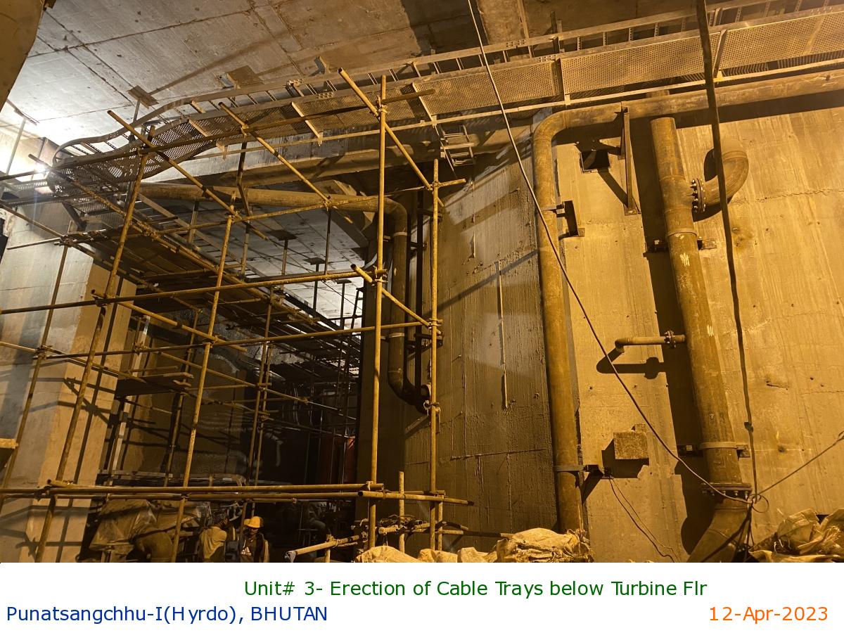
Unit# 3- Erection of Cable Trays below Turbine Flr
|
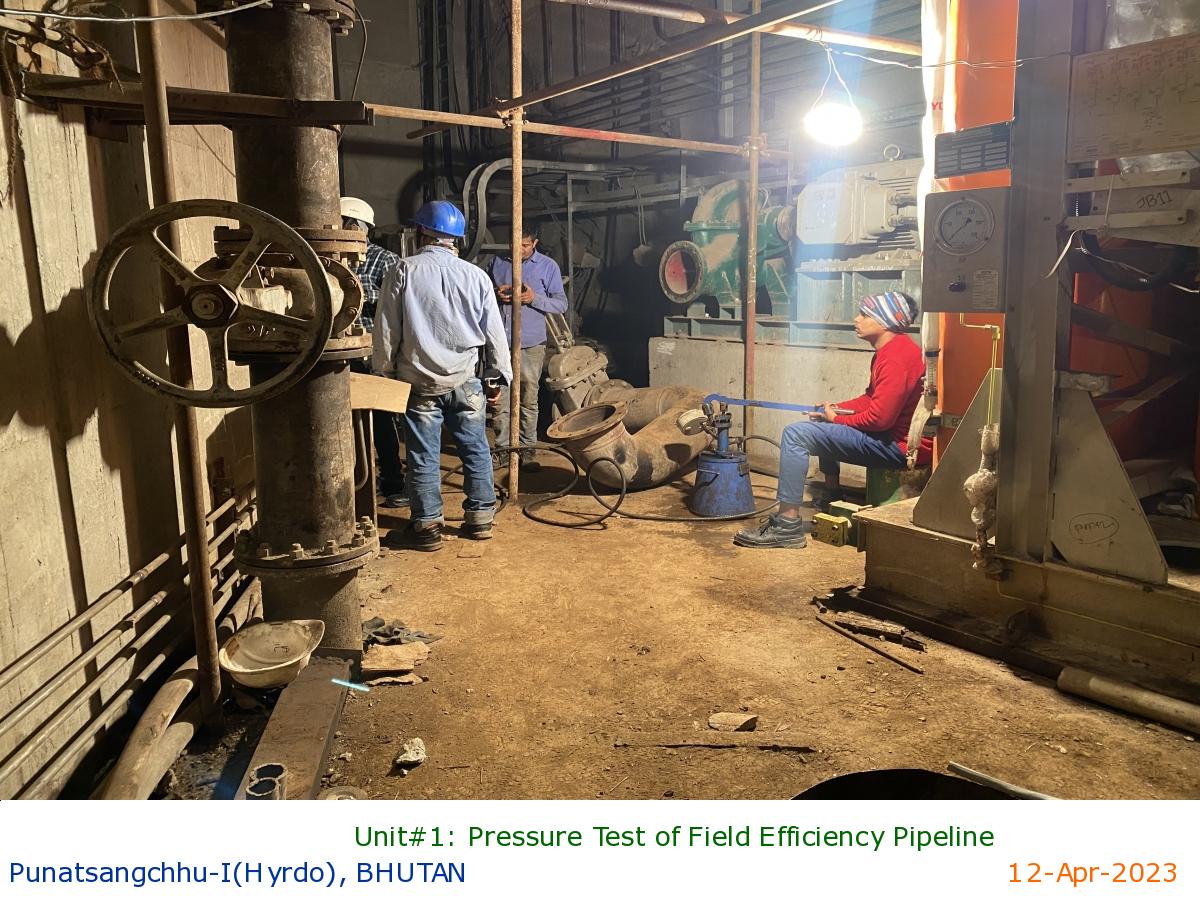
Unit#1: Pressure Test of Field Efficiency Pipeline
|
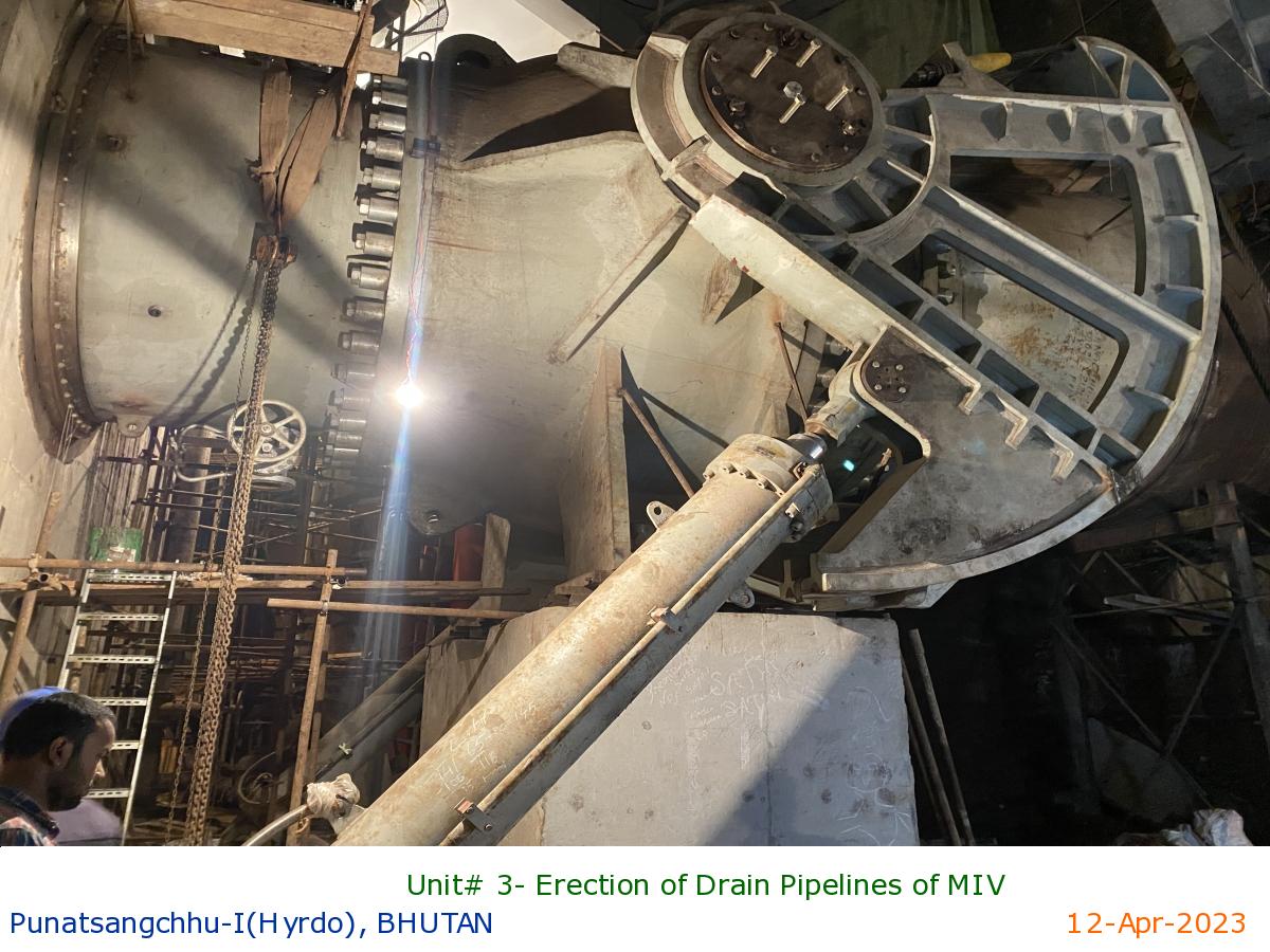
Unit# 3- Erection of Drain Pipelines of MIV
|
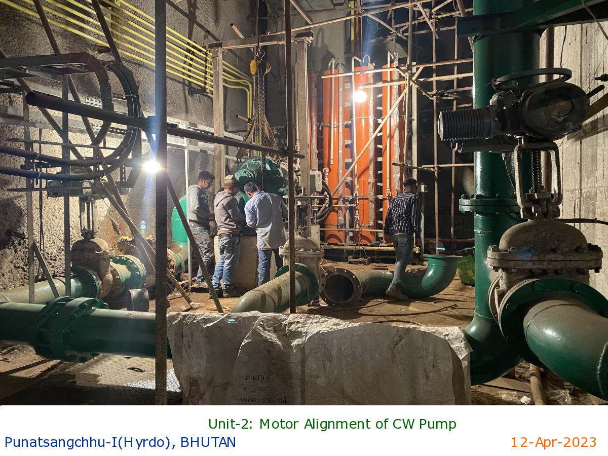
Unit-2: Motor Alignment of CW Pump
|
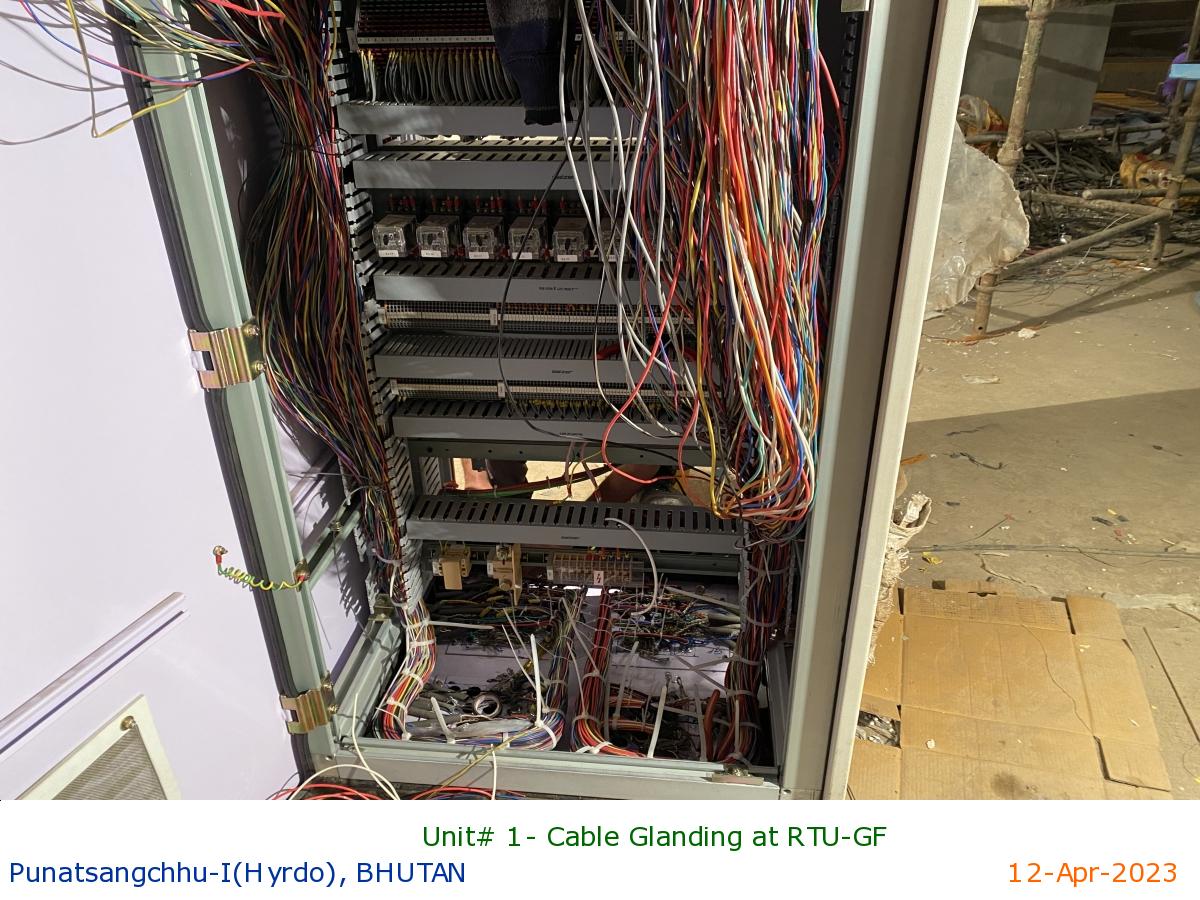
Unit# 1- Cable Glanding at RTU-GF
|
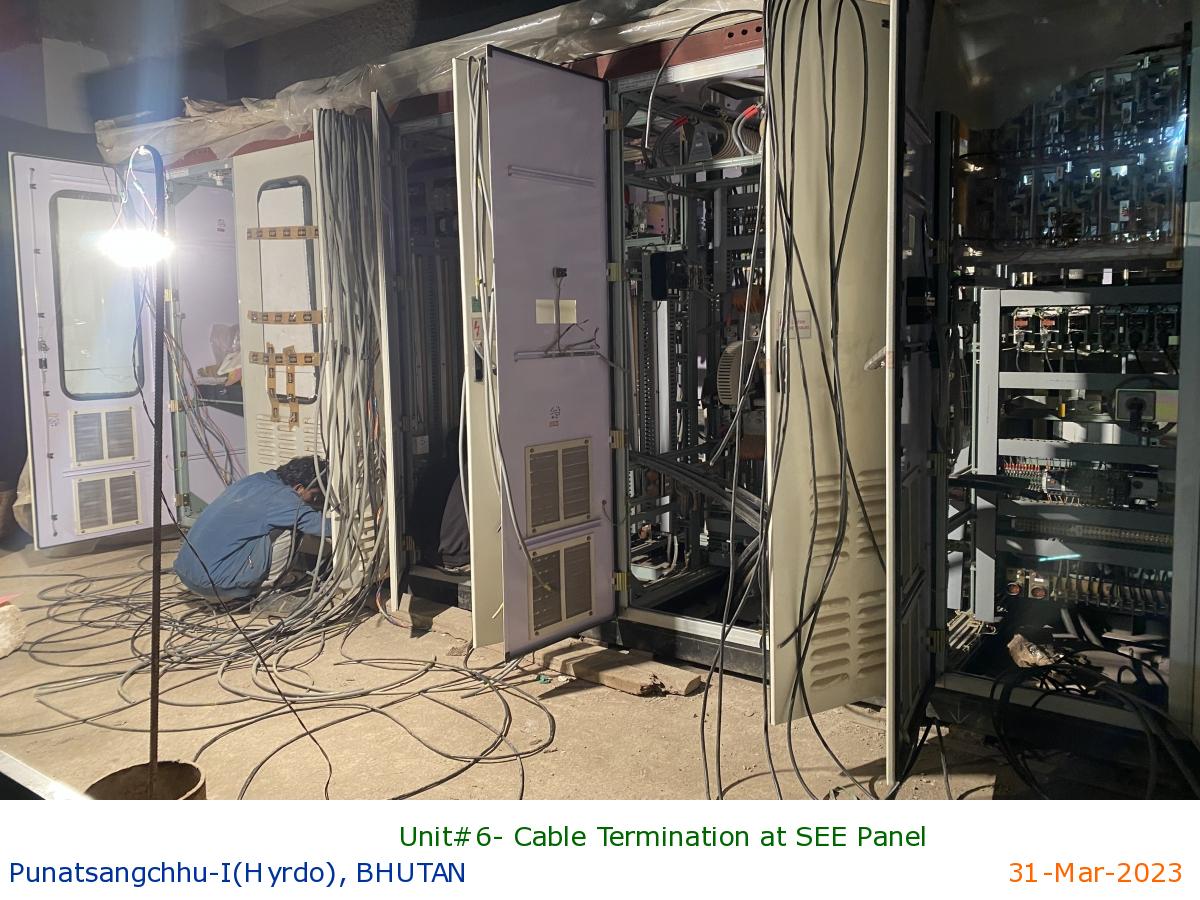
Unit#6- Cable Termination at SEE Panel
|
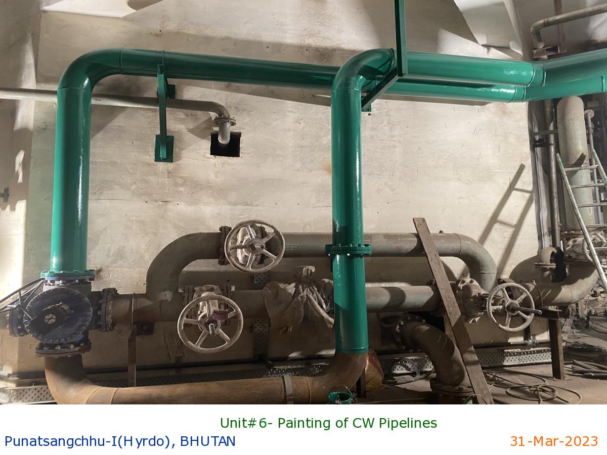
Unit#6- Painting of CW Pipelines
|
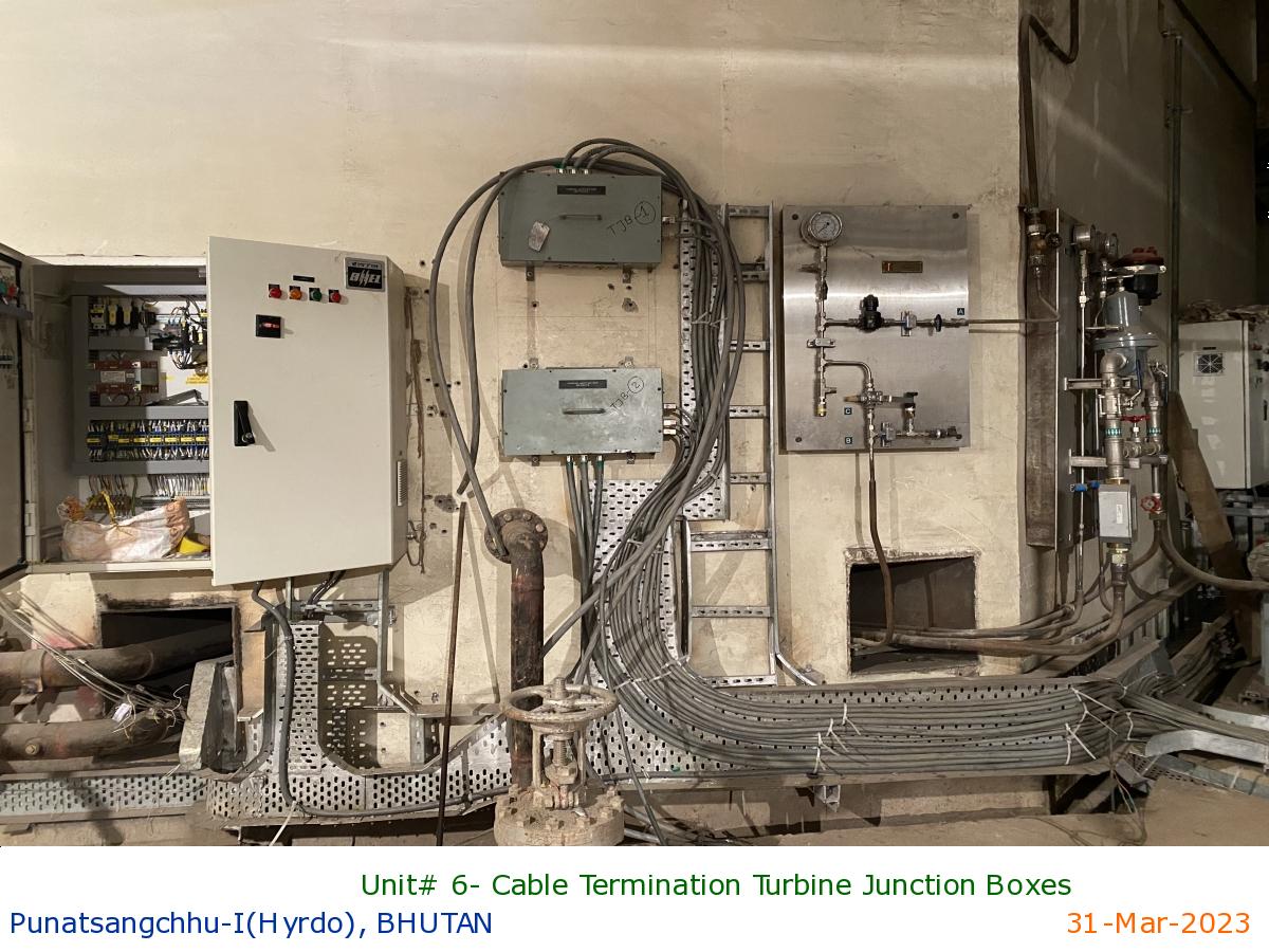
Unit# 6- Cable Termination Turbine Junction Boxes
|
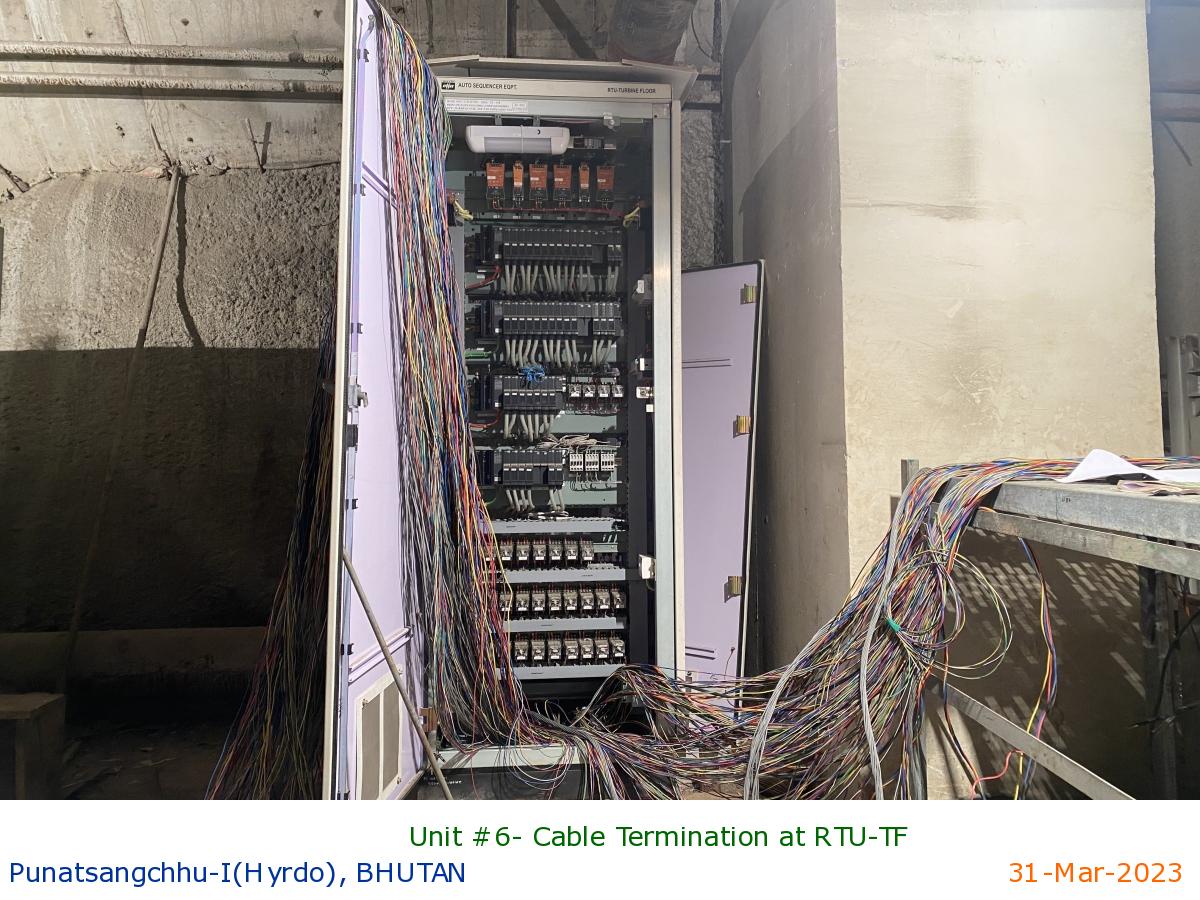
Unit #6- Cable Termination at RTU-TF
|
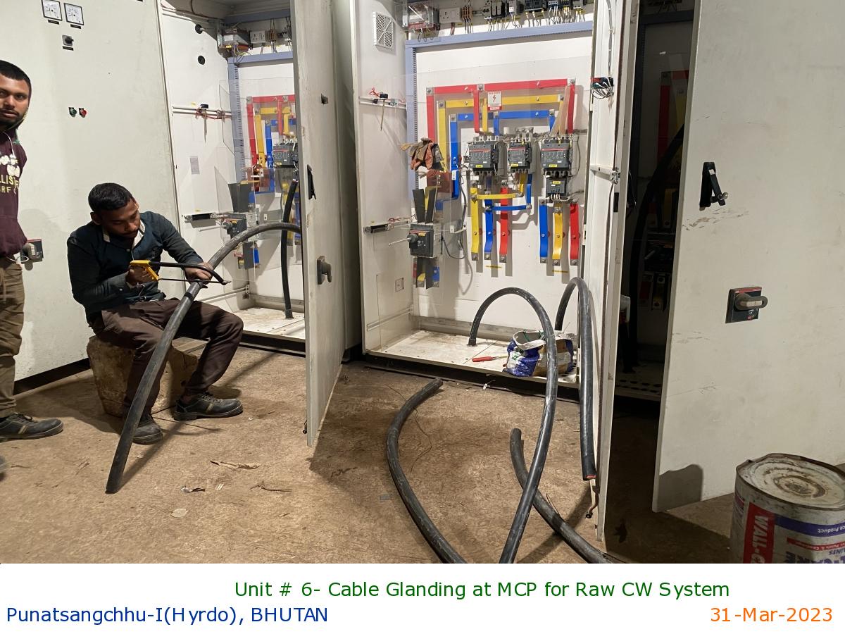
Unit # 6- Cable Glanding at MCP for Raw CW System
|
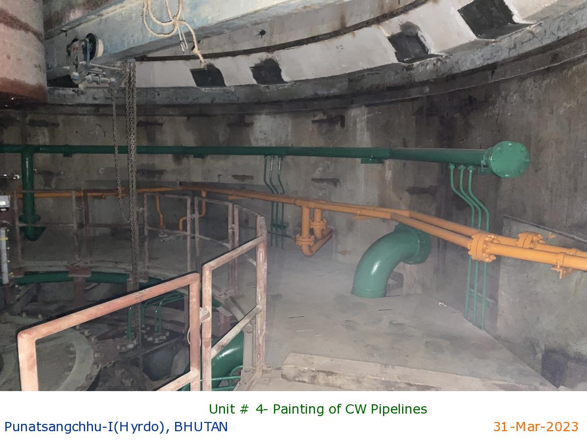
Unit # 4- Painting of CW Pipelines
|
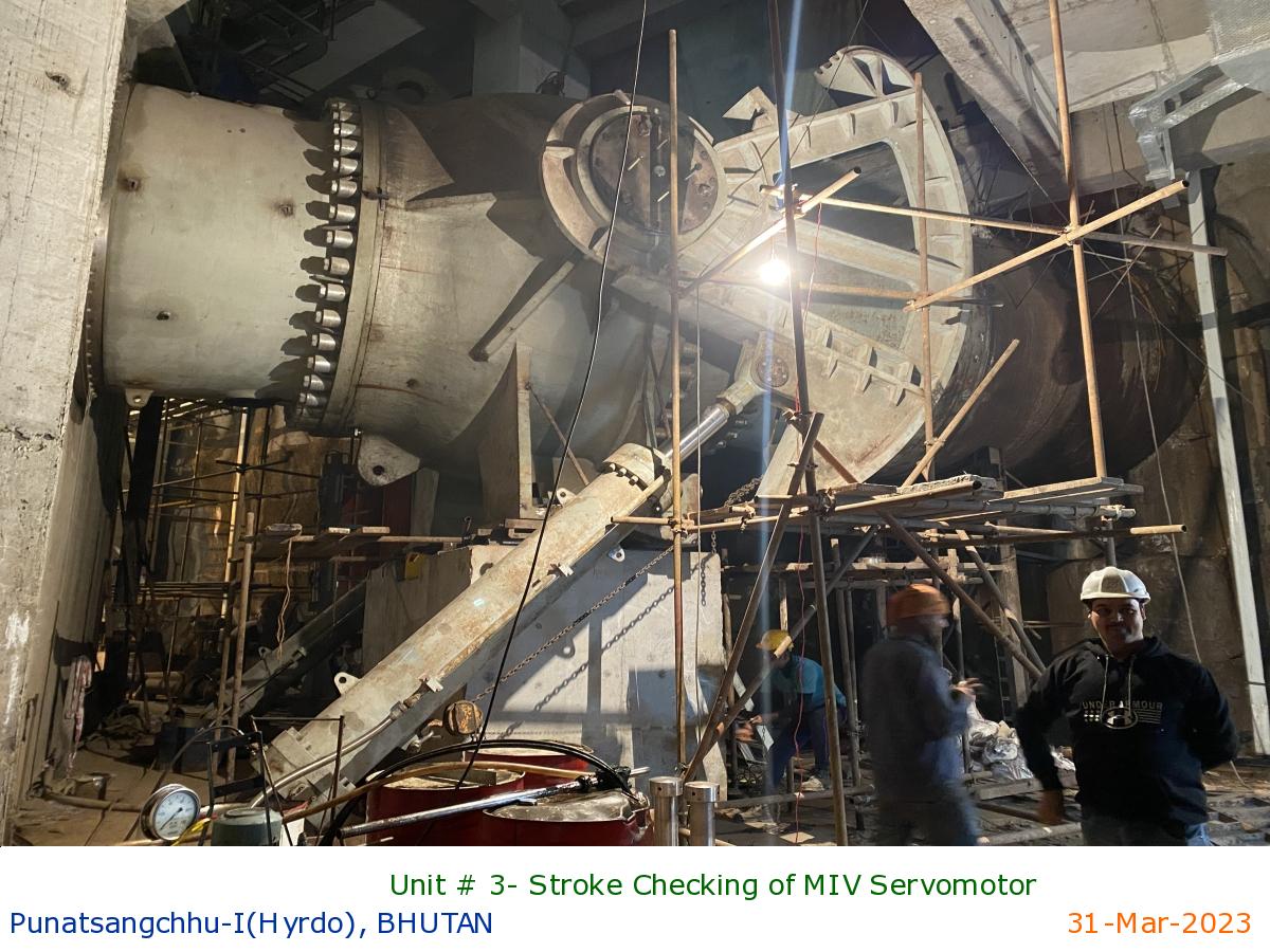
Unit # 3- Stroke Checking of MIV Servomotor
|
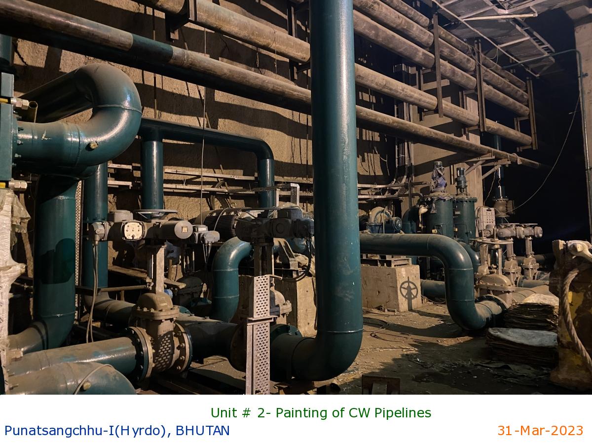
Unit # 2- Painting of CW Pipelines
|
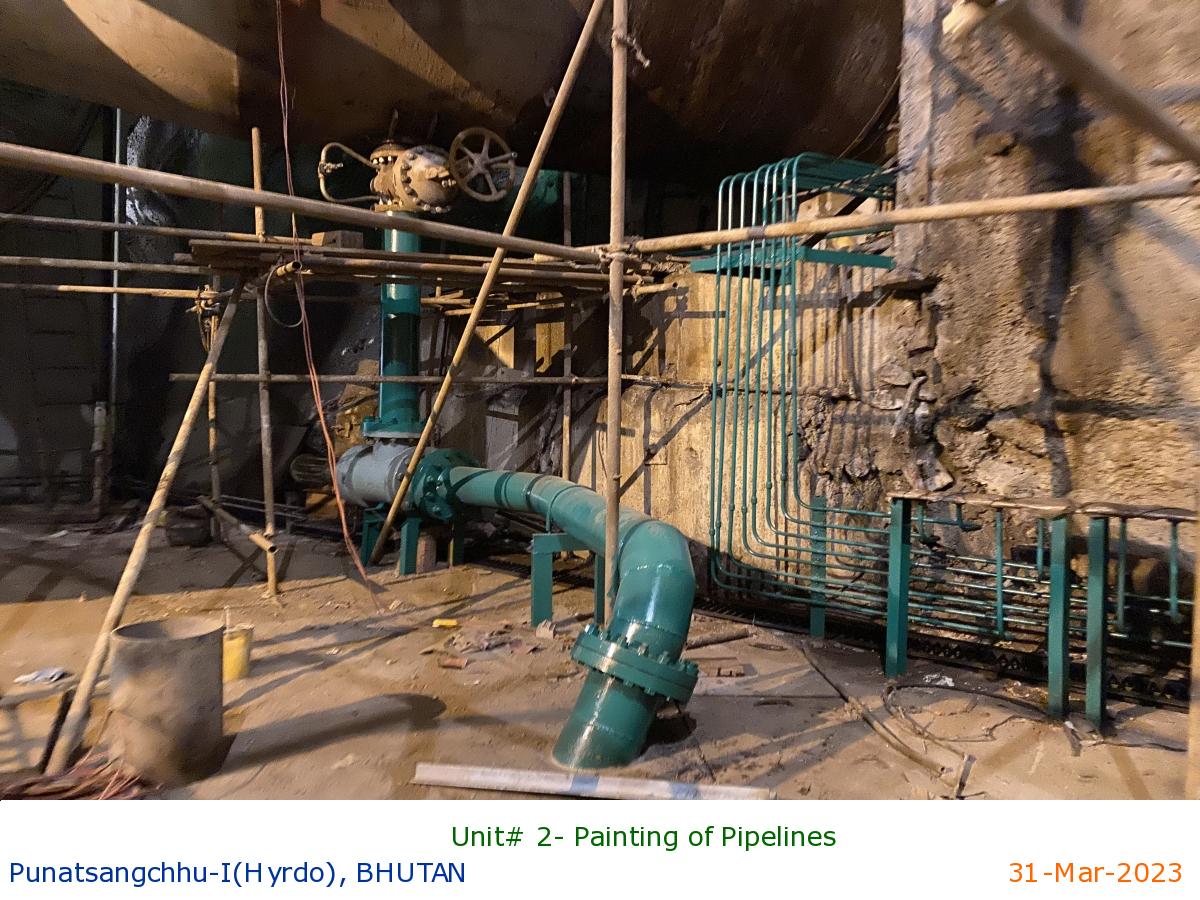
Unit# 2- Painting of Pipelines
|
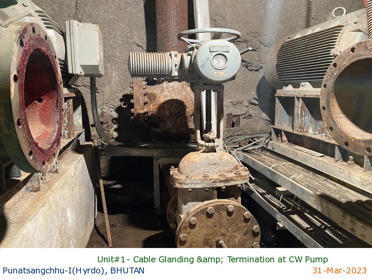
Unit#1- Cable Glanding & Termination at CW Pump
|
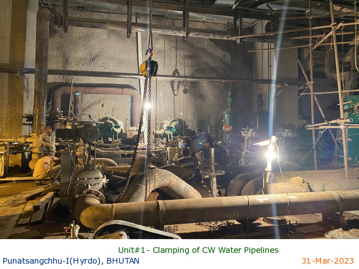
Unit#1- Clamping of CW Water Pipelines
|
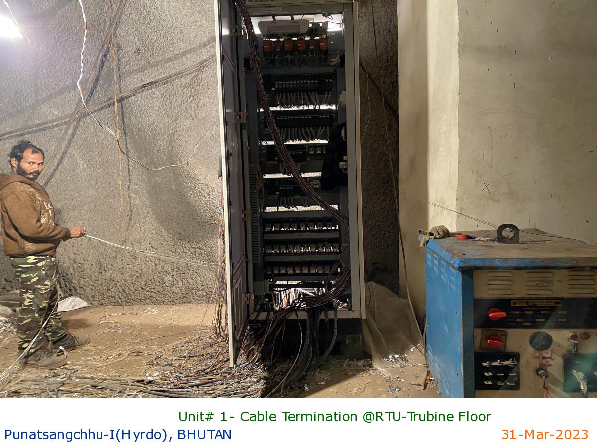
Unit# 1- Cable Termination @RTU-Trubine Floor
|
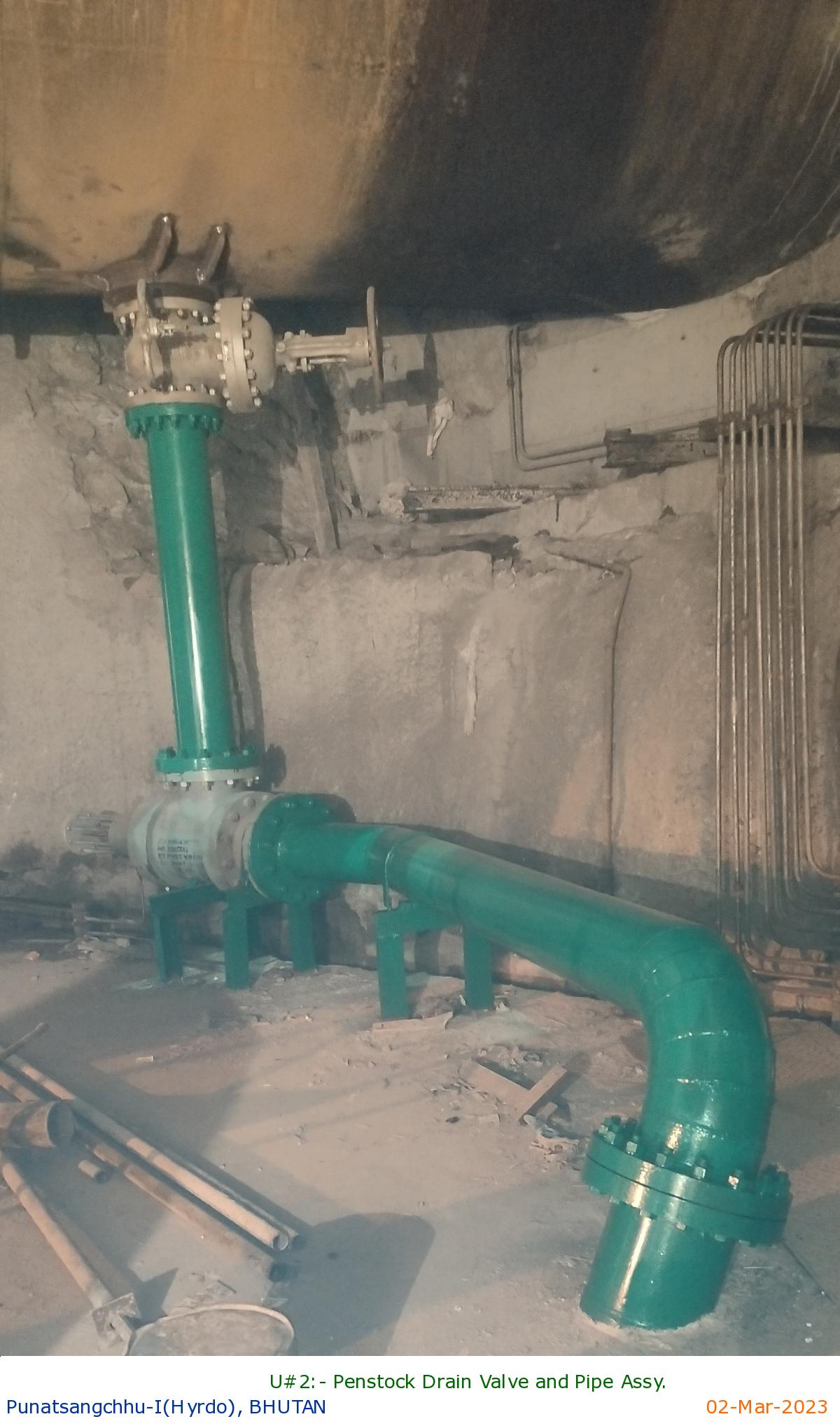
U#2:- Penstock Drain Valve and Pipe Assy.
|
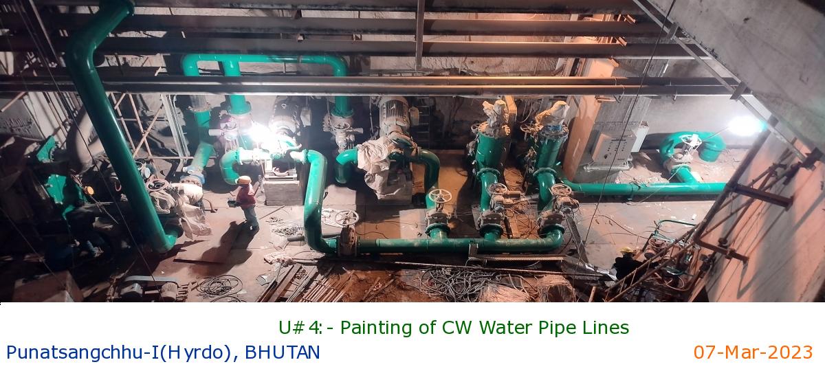
U#4:- Painting of CW Water Pipe Lines
|
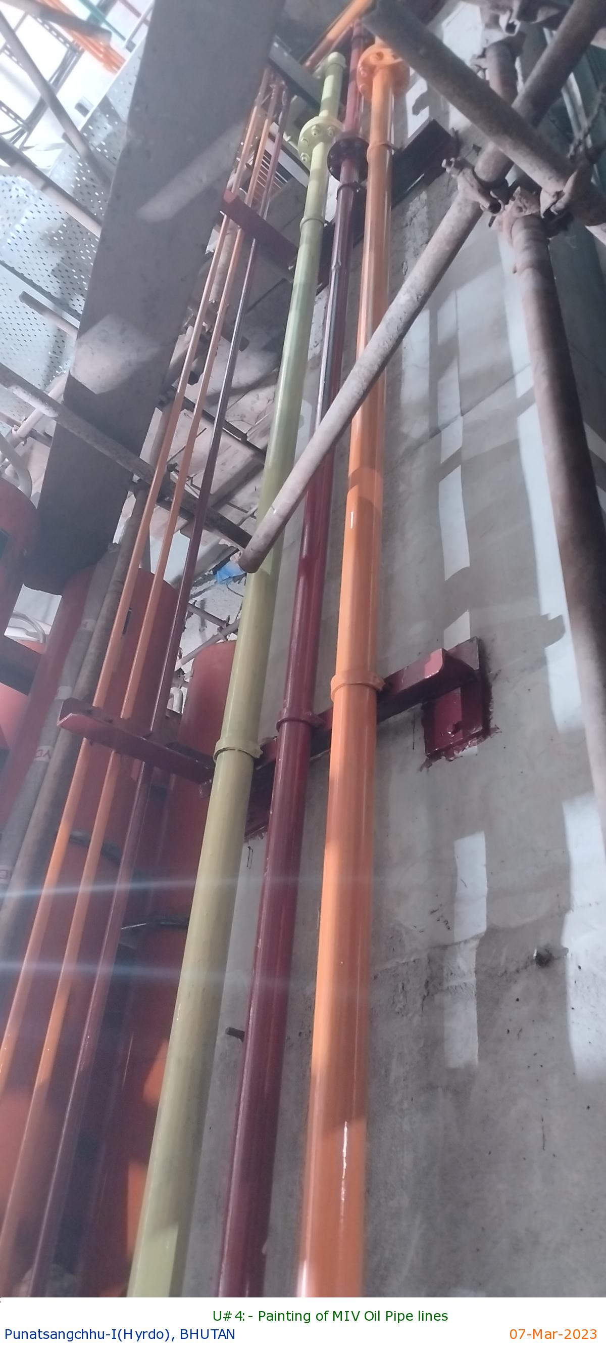
U#4:- Painting of MIV Oil Pipe lines
|
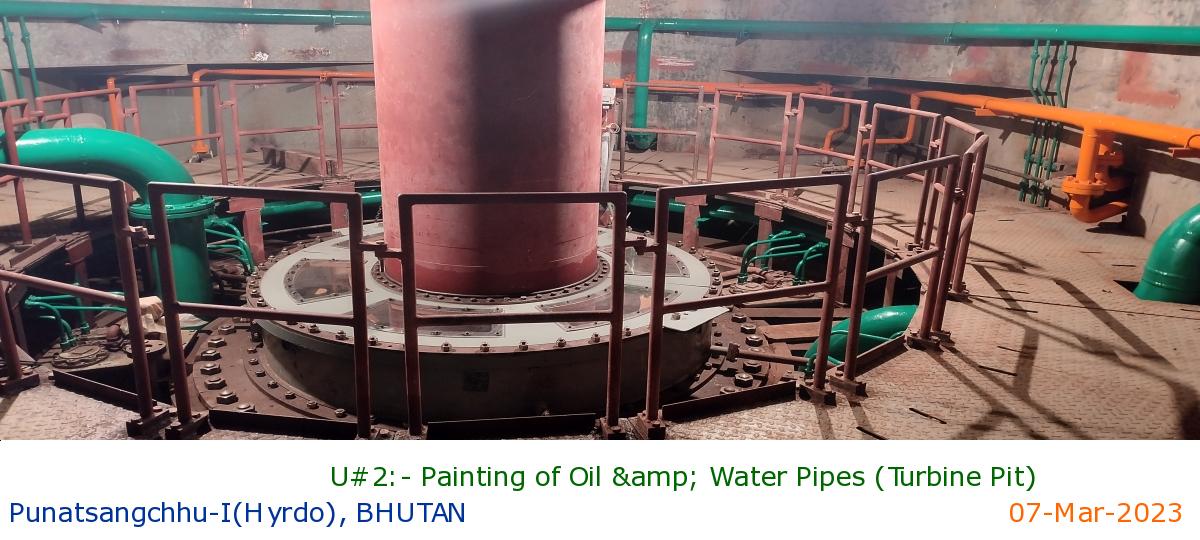
U#2:- Painting of Oil & Water Pipes (Turbine Pit)
|
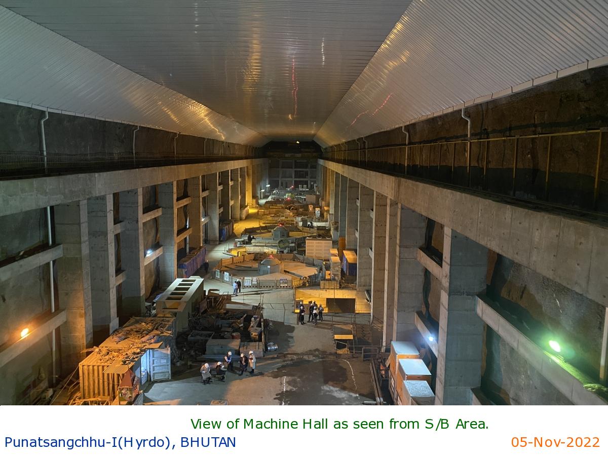
View of Machine Hall as seen from S/B Area.
|
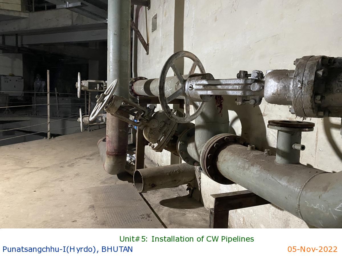
Unit#5: Installation of CW Pipelines
|
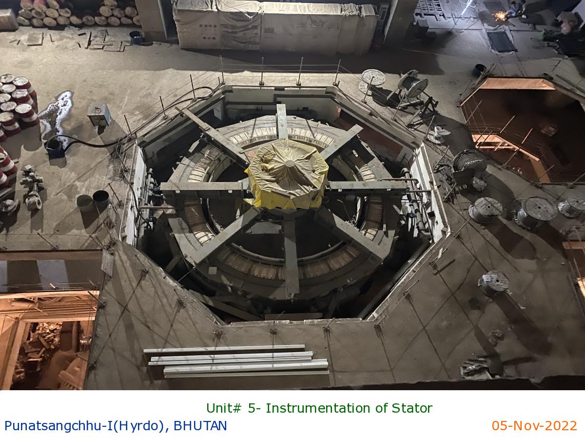
Unit# 5- Instrumentation of Stator
|
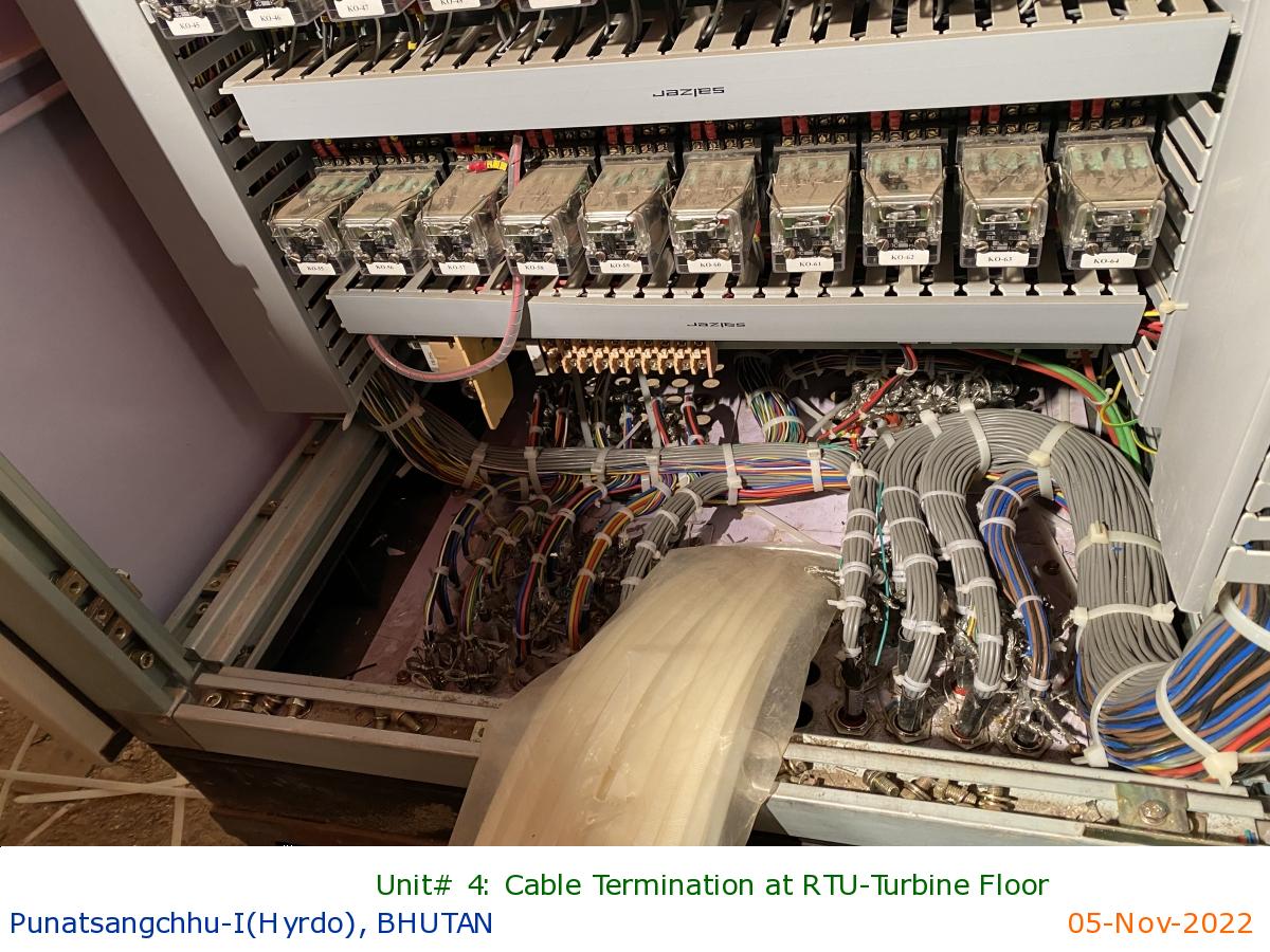
Unit# 4: Cable Termination at RTU-Turbine Floor
|
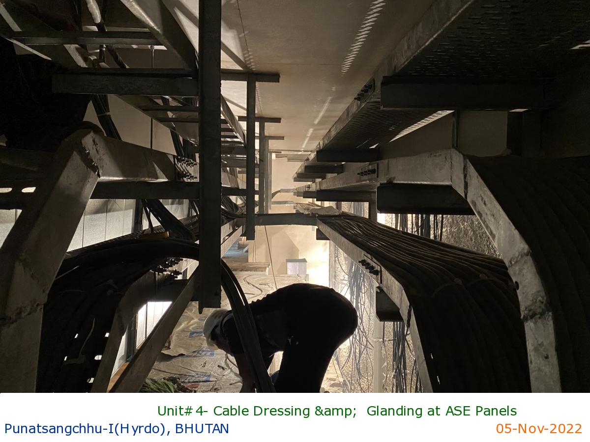
Unit#4- Cable Dressing & Glanding at ASE Panels
|
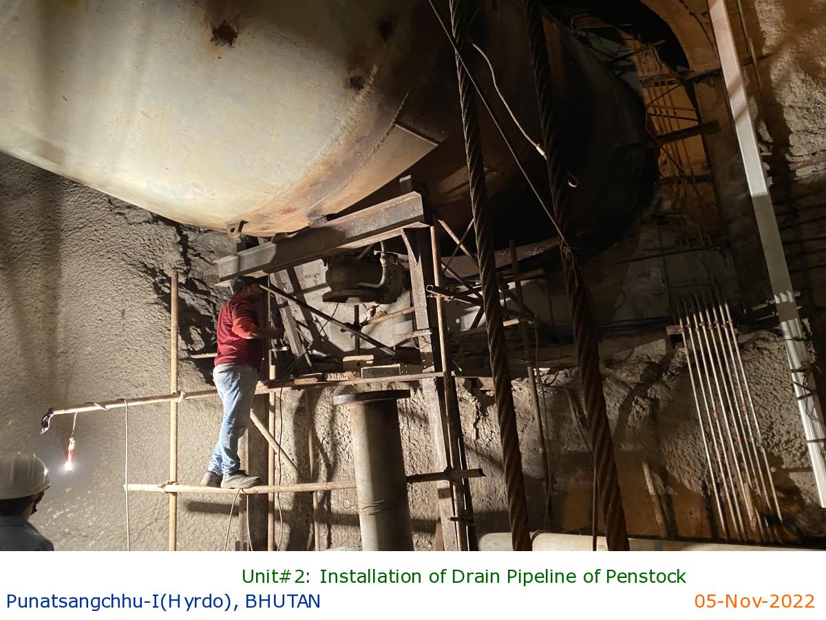
Unit#2: Installation of Drain Pipeline of Penstock
|
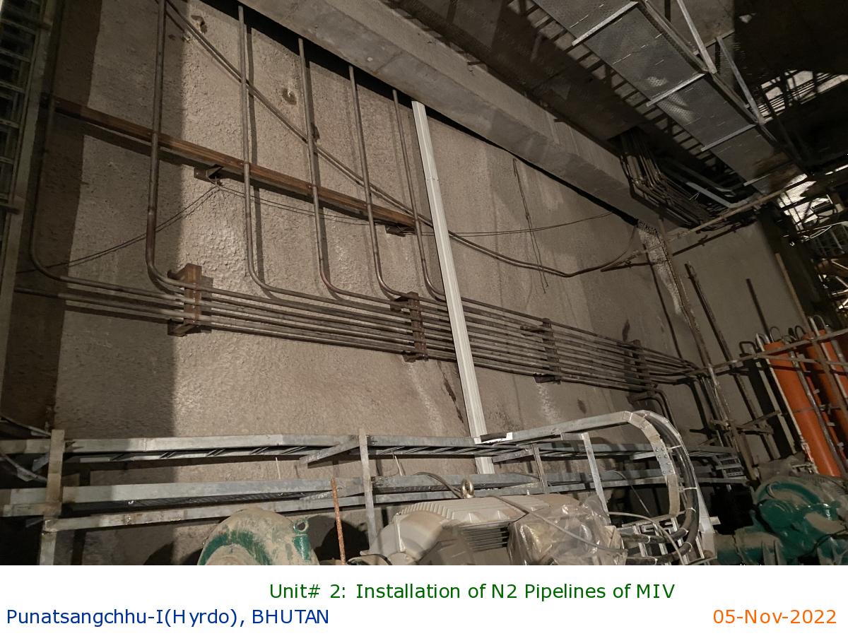
Unit# 2: Installation of N2 Pipelines of MIV
|
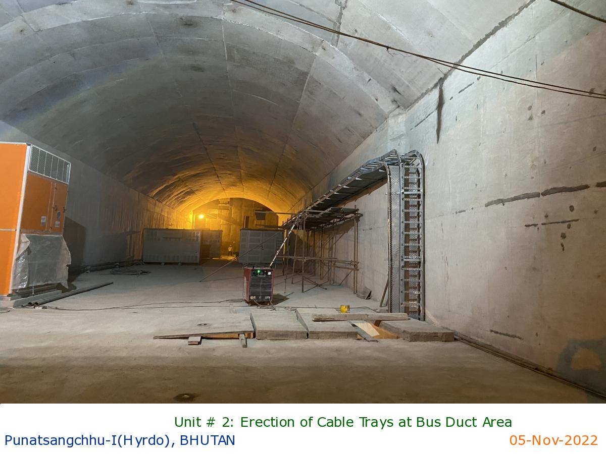
Unit # 2: Erection of Cable Trays at Bus Duct Area
|
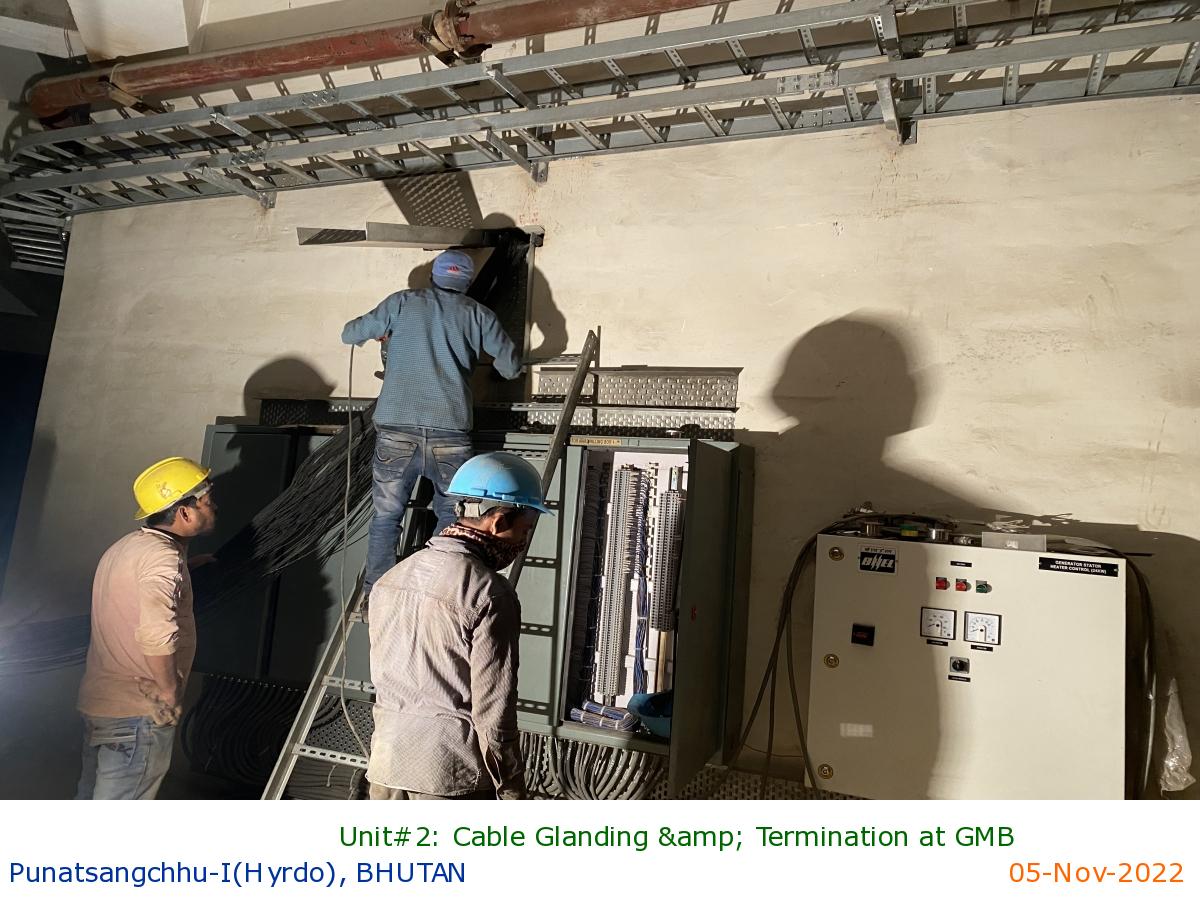
Unit#2: Cable Glanding & Termination at GMB
|
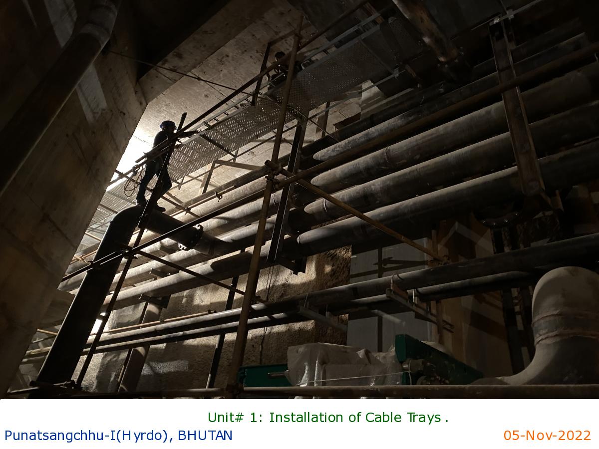
Unit# 1: Installation of Cable Trays .
|
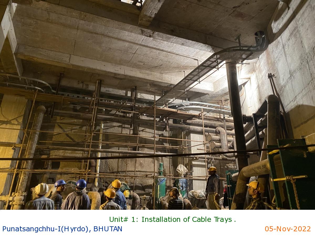
Unit# 1: Installation of Cable Trays .
|
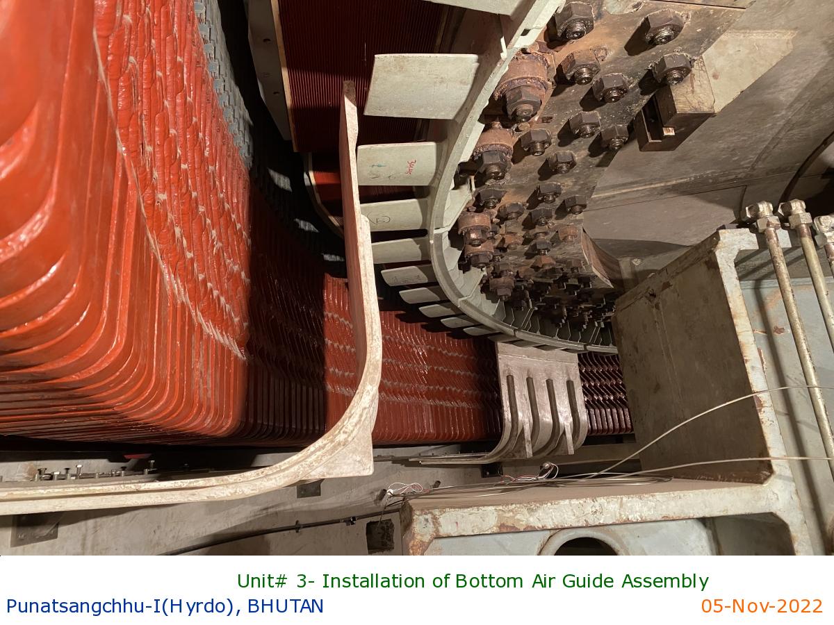
Unit# 3- Installation of Bottom Air Guide Assembly
|
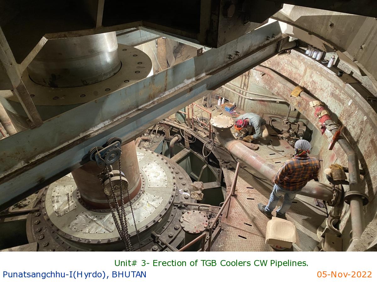
Unit# 3- Erection of TGB Coolers CW Pipelines.
|
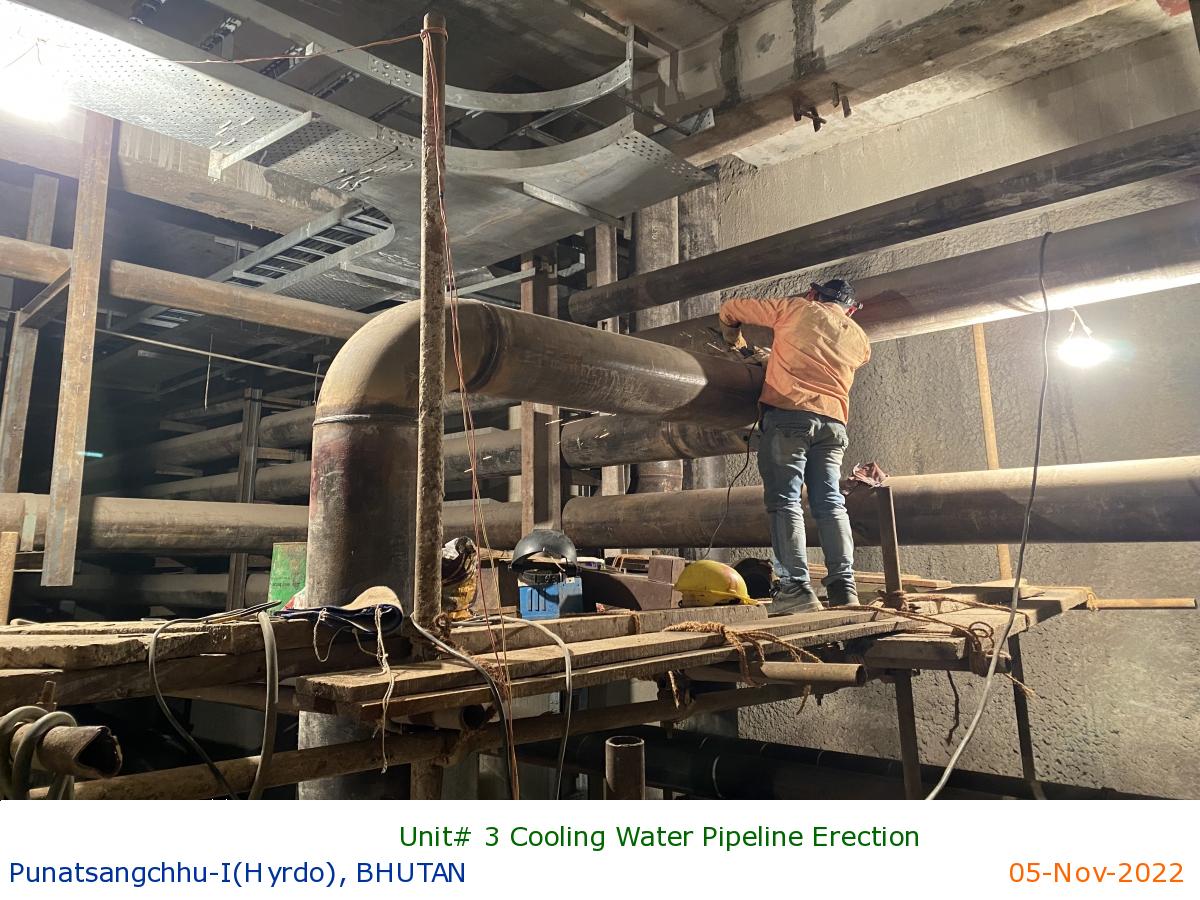
Unit# 3 Cooling Water Pipeline Erection
|
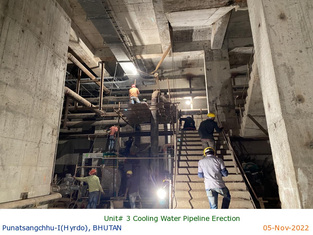
Unit# 3 Cooling Water Pipeline Erection
|
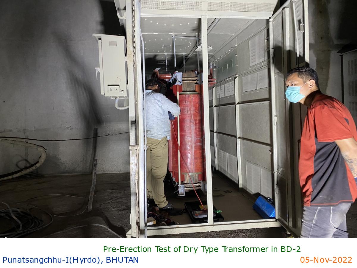
Pre-Erection Test of Dry Type Transformer in BD-2
|
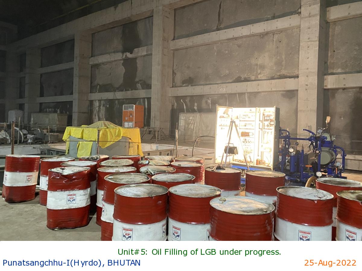
Unit#5: Oil Filling of LGB under progress.
|
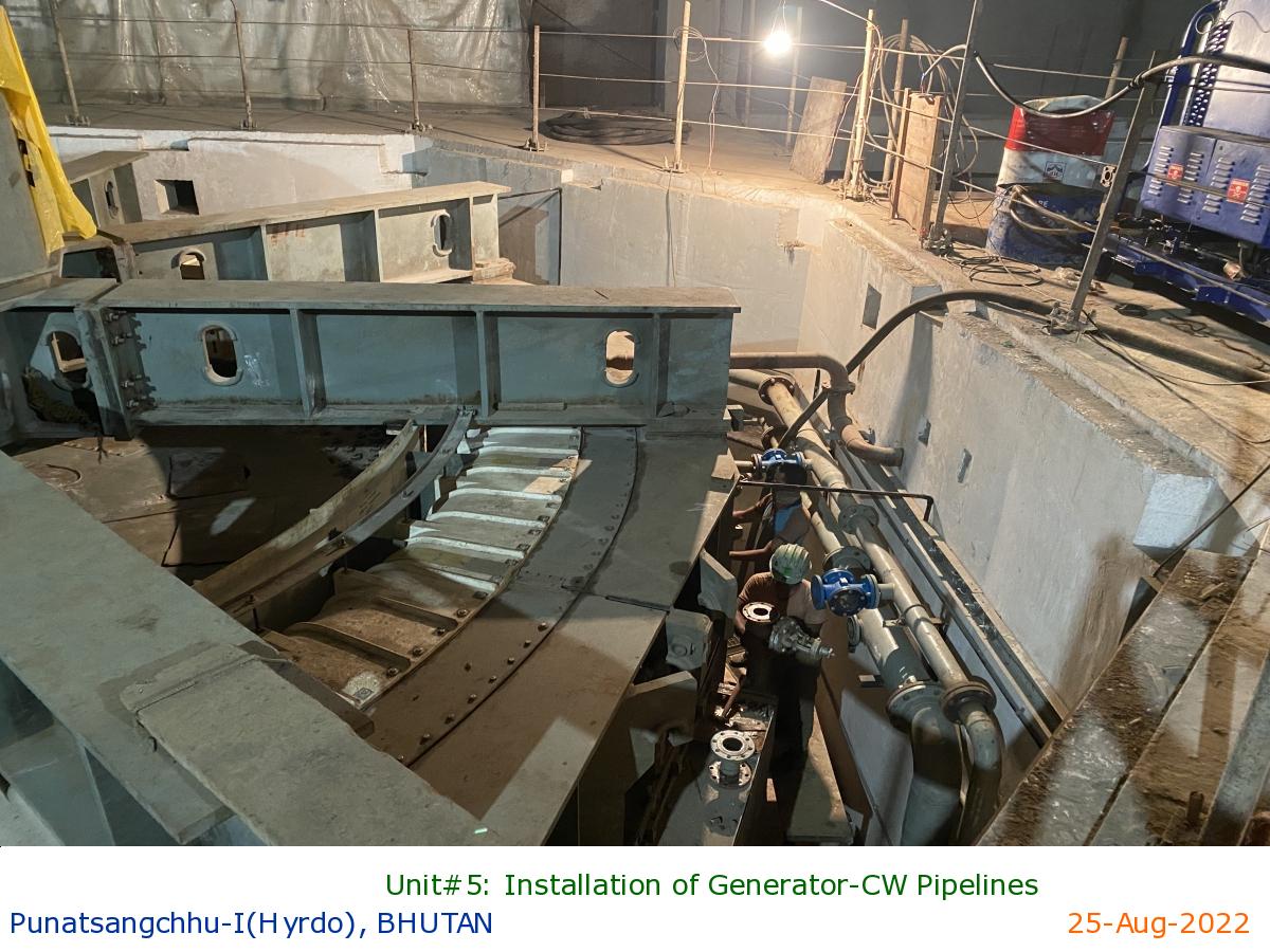
Unit#5: Installation of Generator-CW Pipelines
|
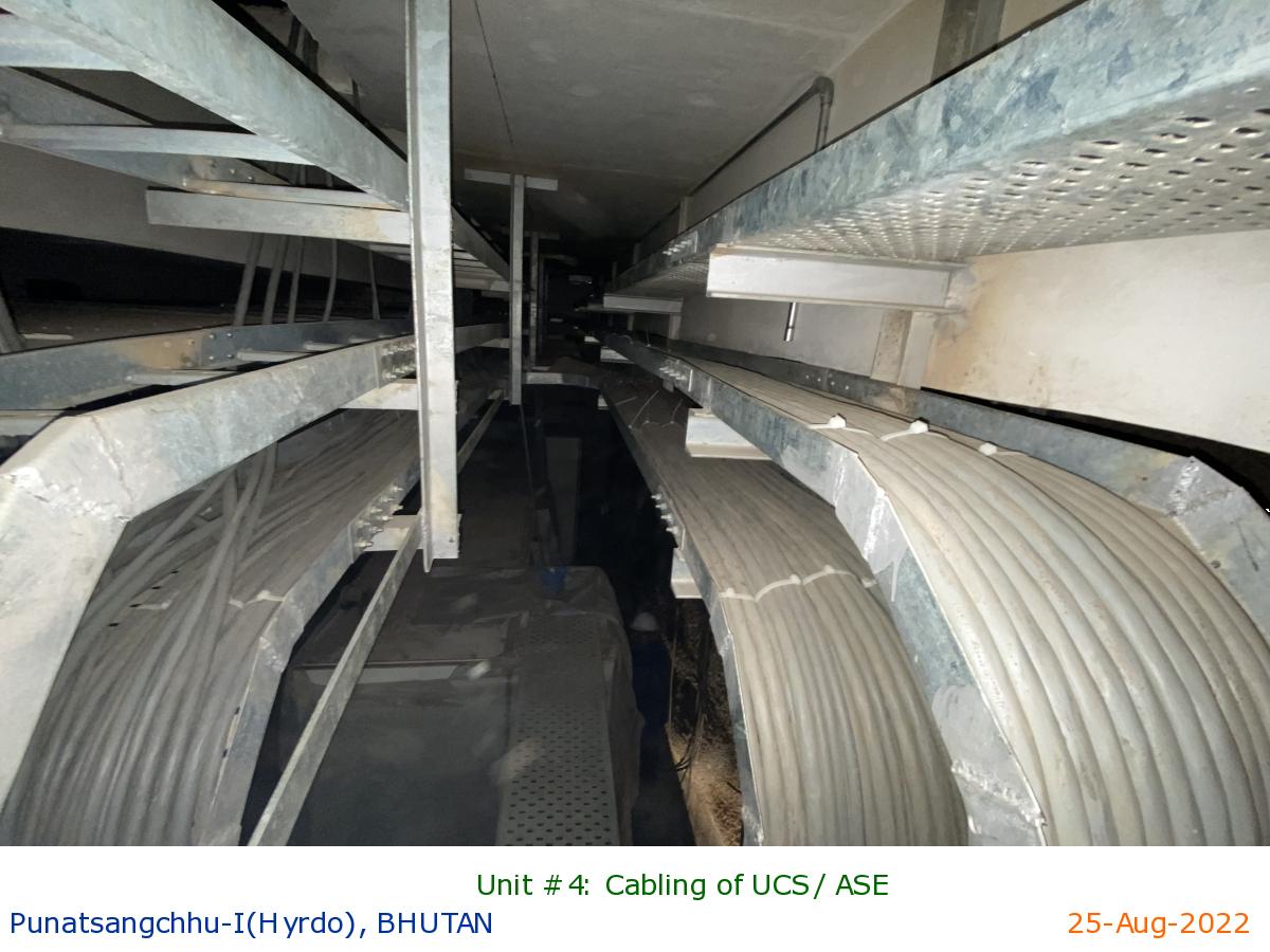
Unit #4: Cabling of UCS/ ASE
|
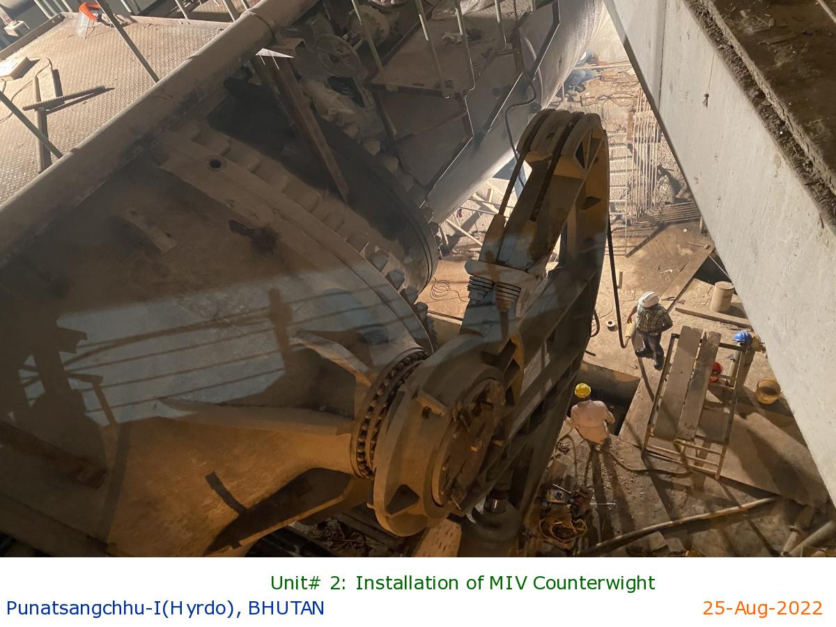
Unit# 2: Installation of MIV Counterwight
|
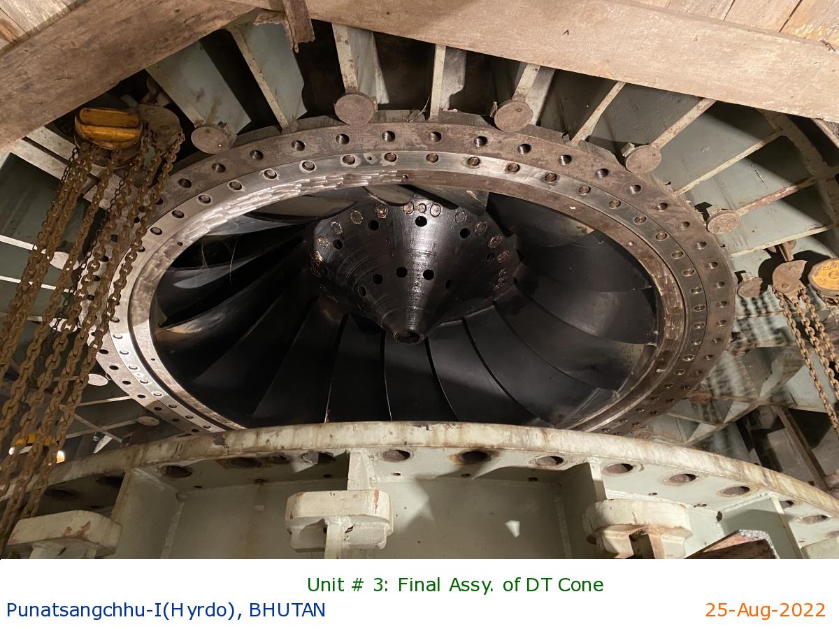
Unit # 3: Final Assy. of DT Cone
|
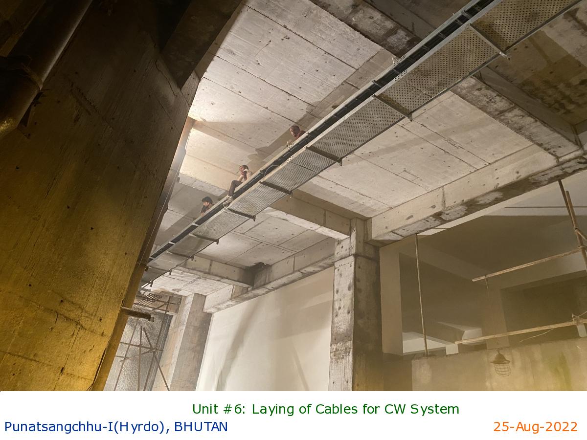
Unit #6: Laying of Cables for CW System
|
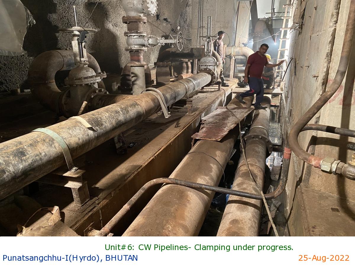
Unit#6: CW Pipelines- Clamping under progress.
|
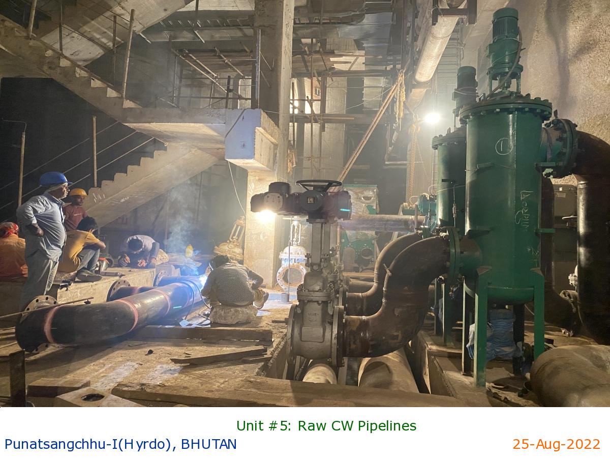
Unit #5: Raw CW Pipelines
|
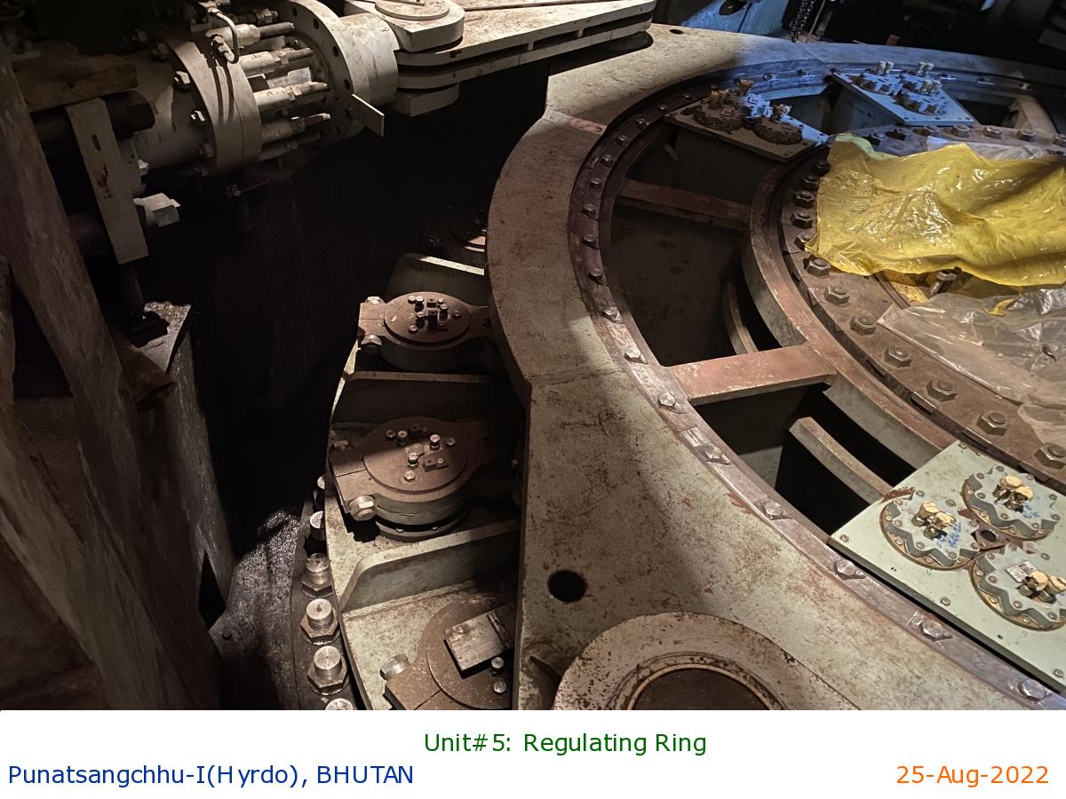
Unit#5: Regulating Ring
|
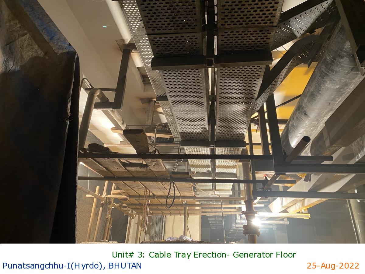
Unit# 3: Cable Tray Erection- Generator Floor
|
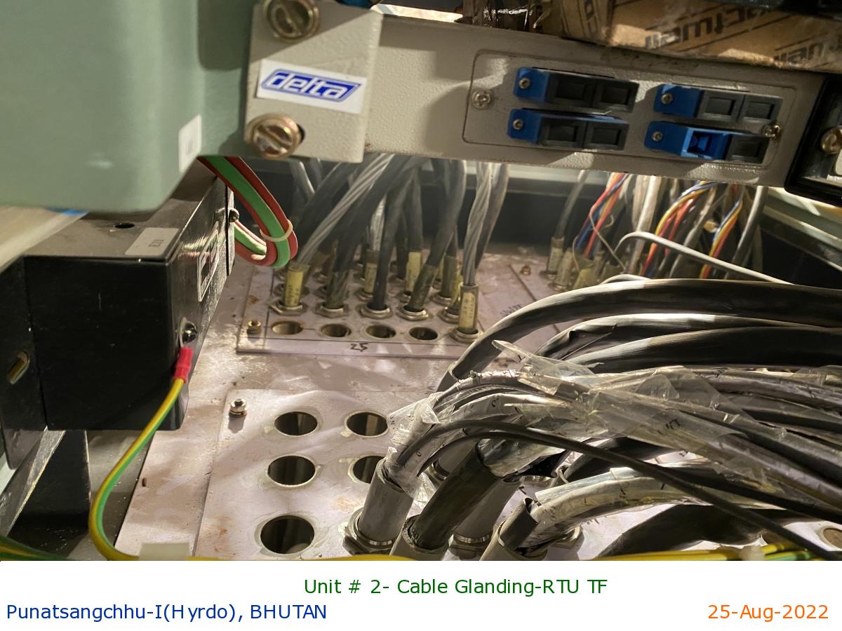
Unit # 2- Cable Glanding-RTU TF
|
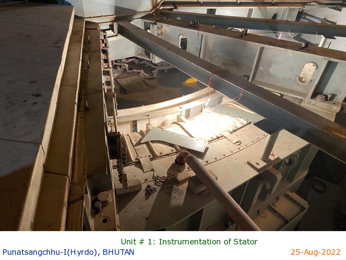
Unit # 1: Instrumentation of Stator
|
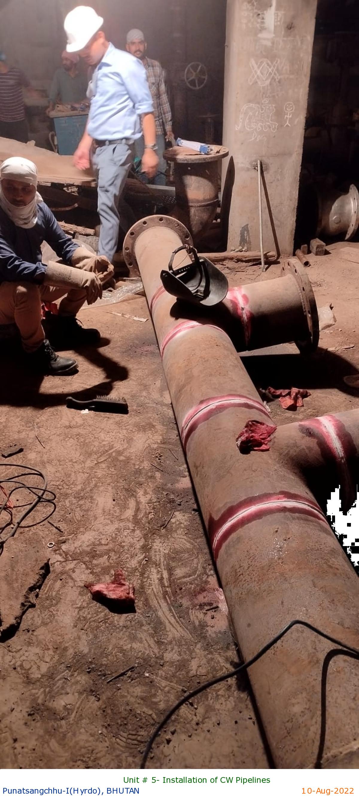
Unit # 5- Installation of CW Pipelines
|
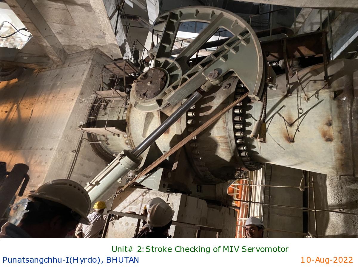
Unit# 2:Stroke Checking of MIV Servomotor
|

Unit # 5: Installation of LGB Oil Coolers
|
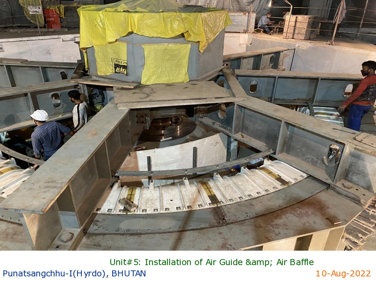
Unit#5: Installation of Air Guide & Air Baffle
|
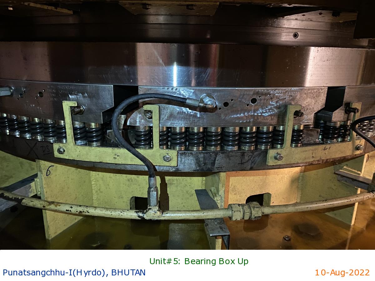
Unit#5: Bearing Box Up
|
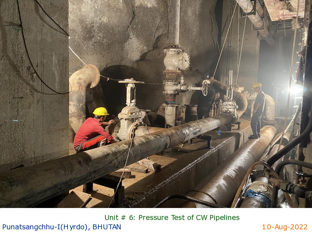
Unit # 6: Pressure Test of CW Pipelines
|
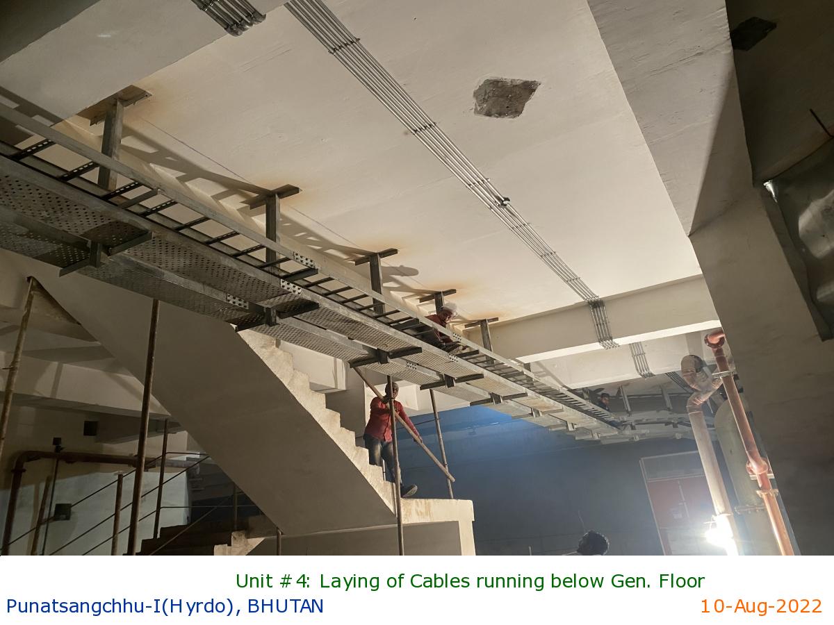
Unit #4: Laying of Cables running below Gen. Floor
|
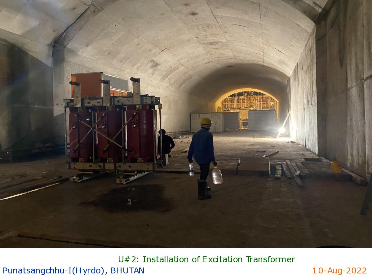
U#2: Installation of Excitation Transformer
|
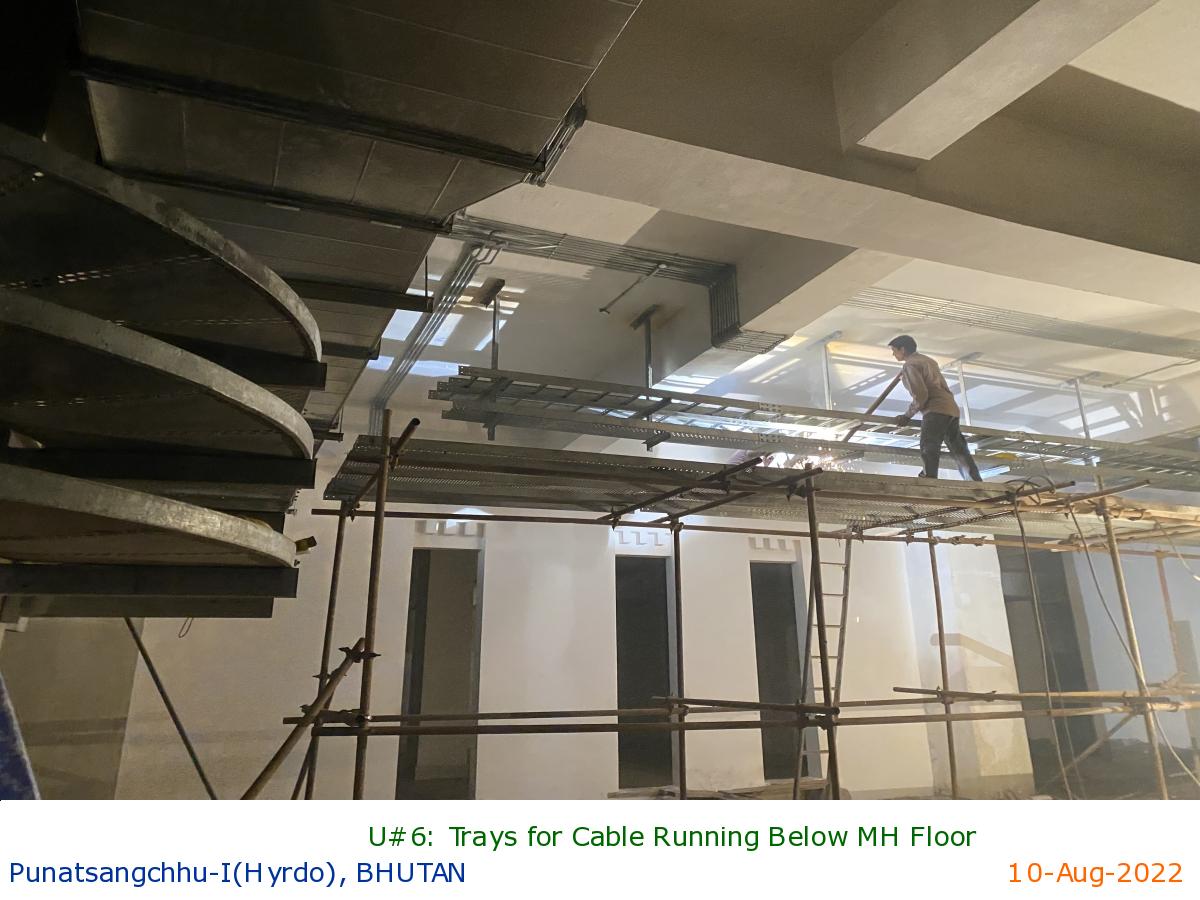
U#6: Trays for Cable Running Below MH Floor
|
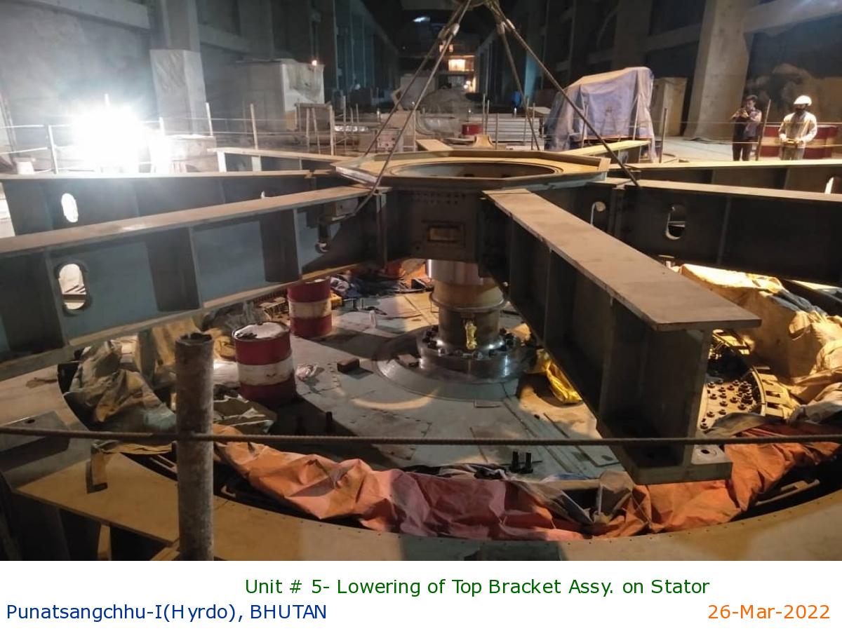
Unit # 5- Lowering of Top Bracket Assy. on Stator
|
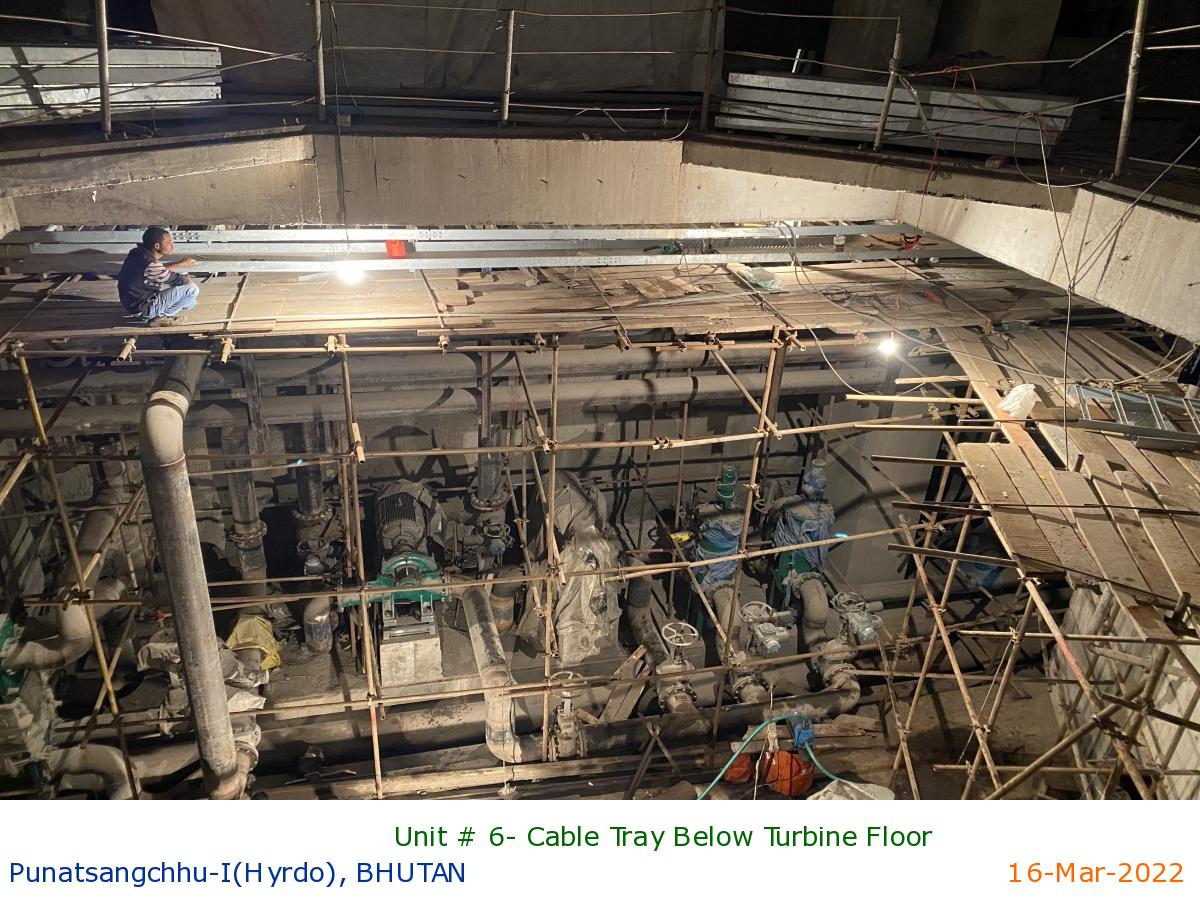
Unit # 6- Cable Tray Below Turbine Floor
|
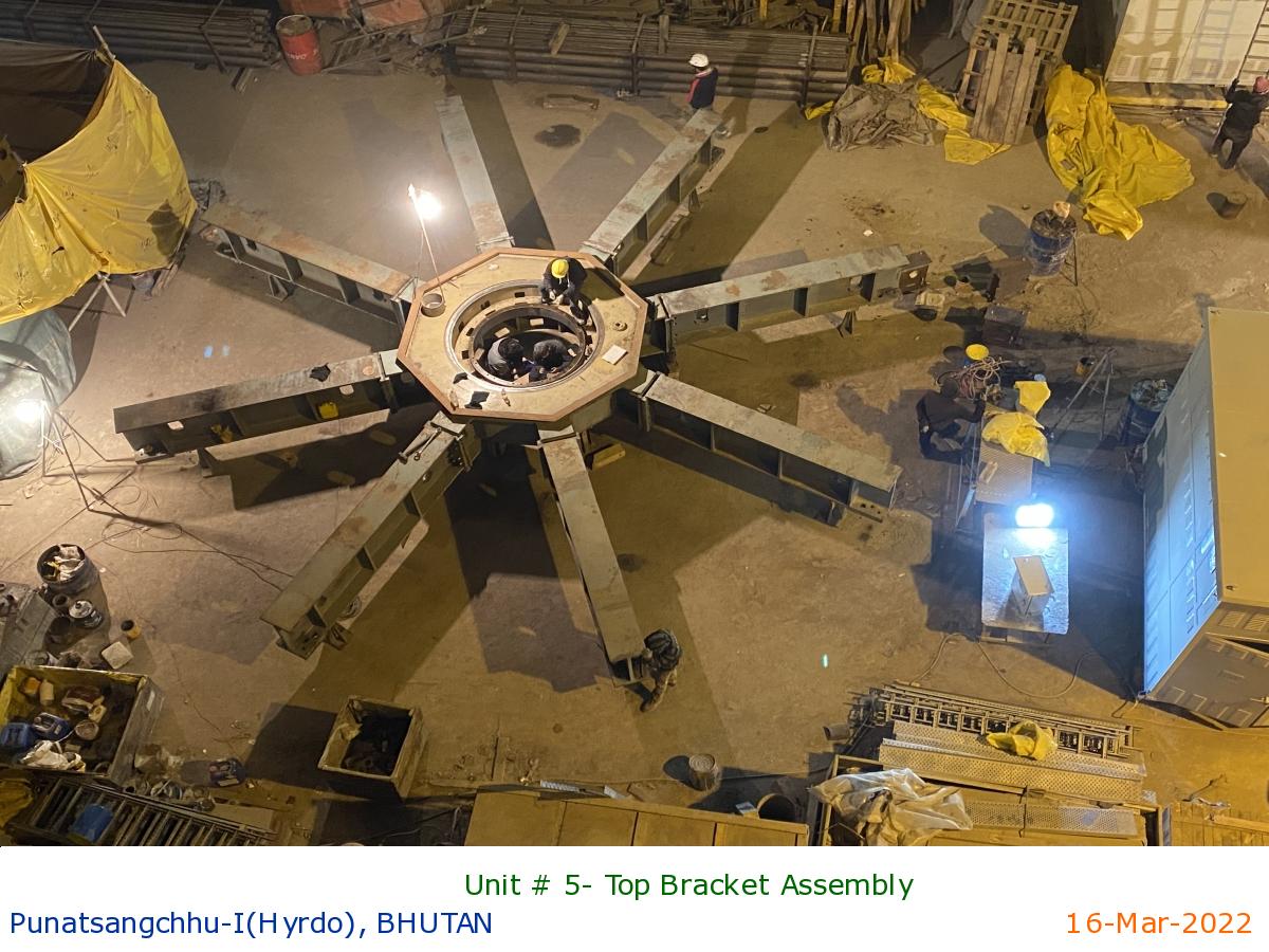
Unit # 5- Top Bracket Assembly
|
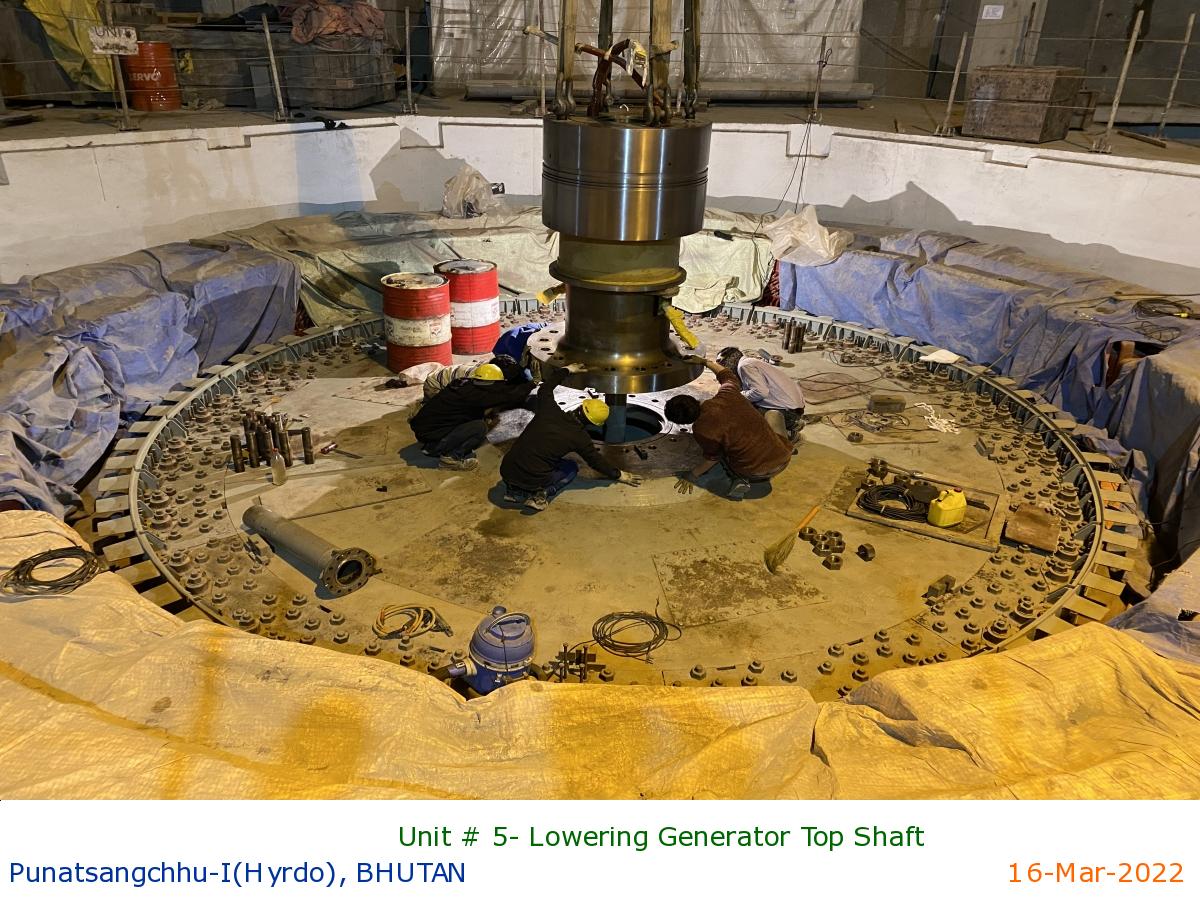
Unit # 5- Lowering Generator Top Shaft
|
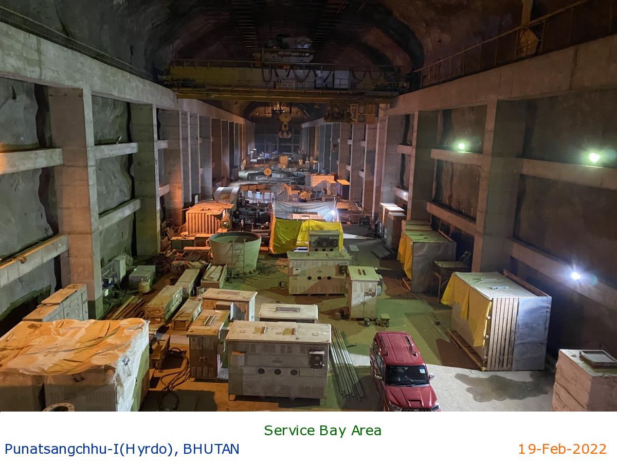
Service Bay Area
|
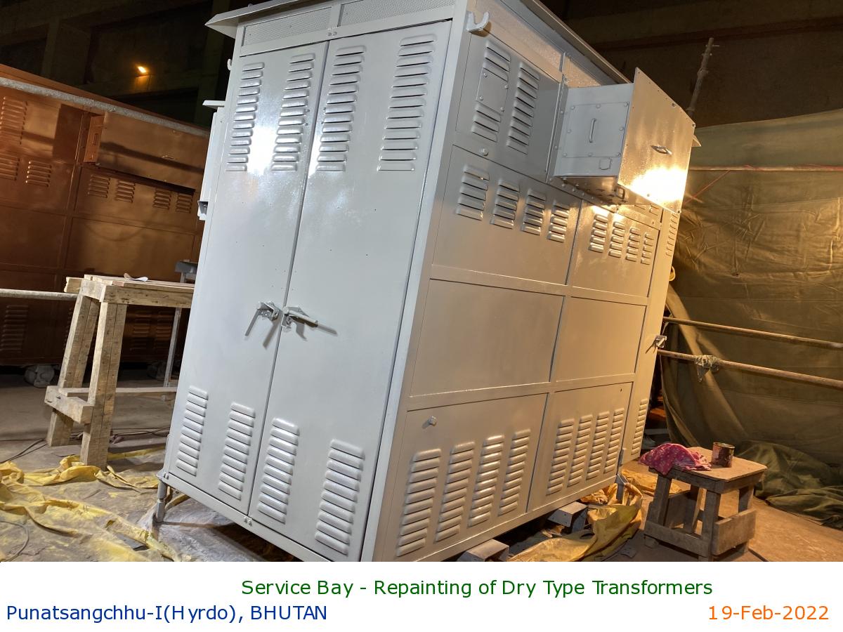
Service Bay - Repainting of Dry Type Transformers
|
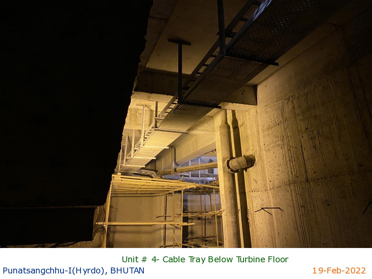
Unit # 4- Cable Tray Below Turbine Floor
|
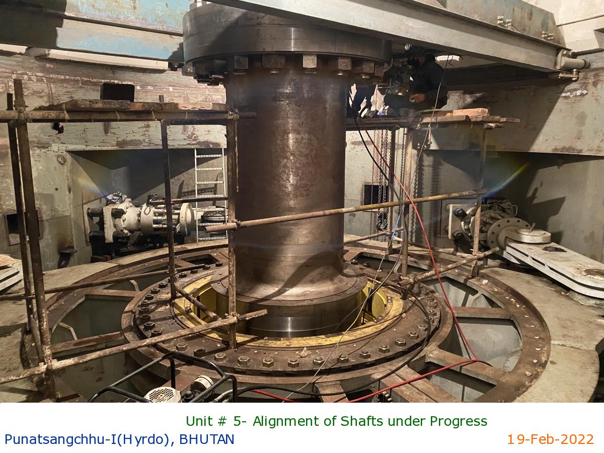
Unit # 5- Alignment of Shafts under Progress
|
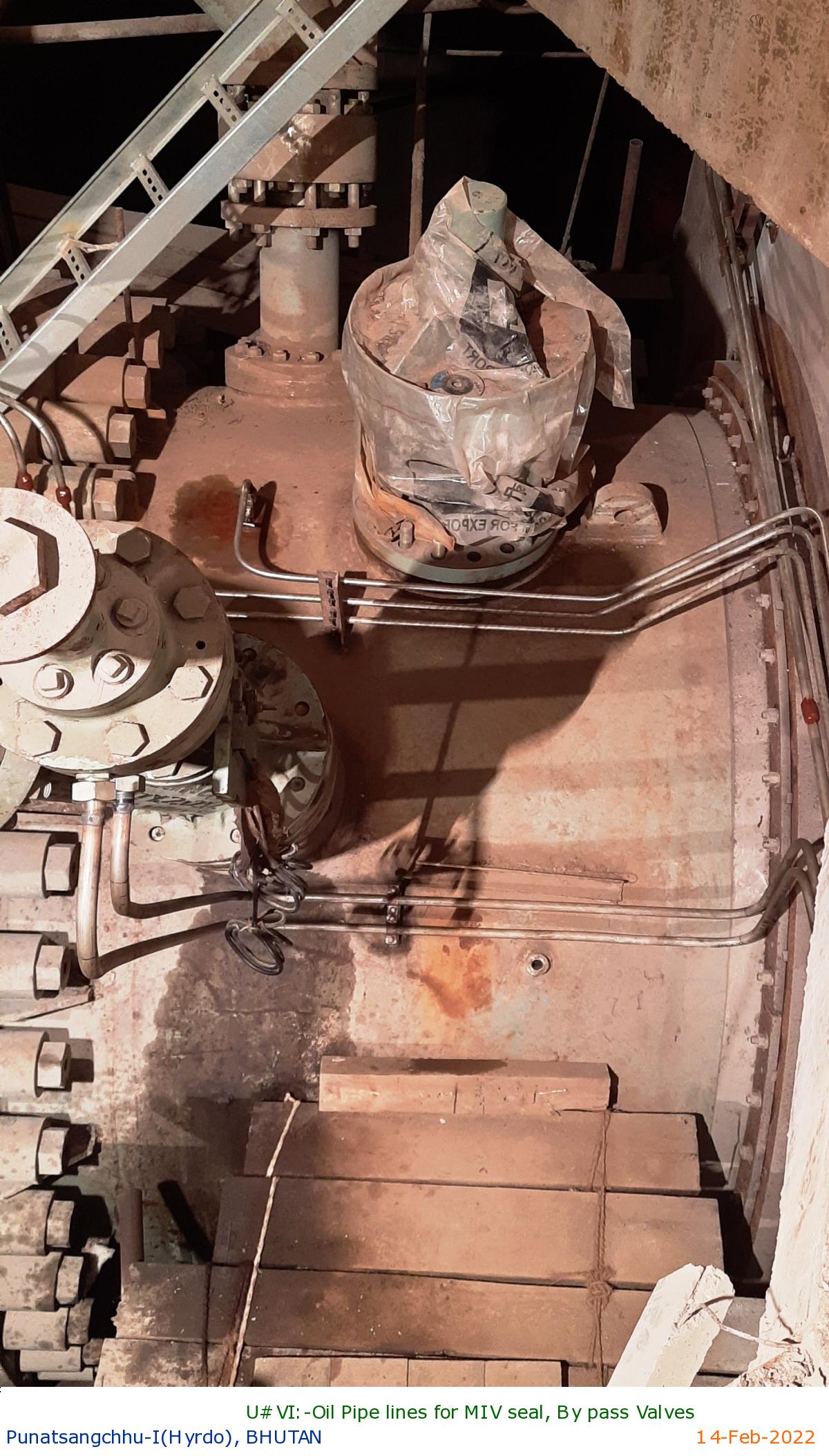
U#VI:-Oil Pipe lines for MIV seal, By pass Valves
|
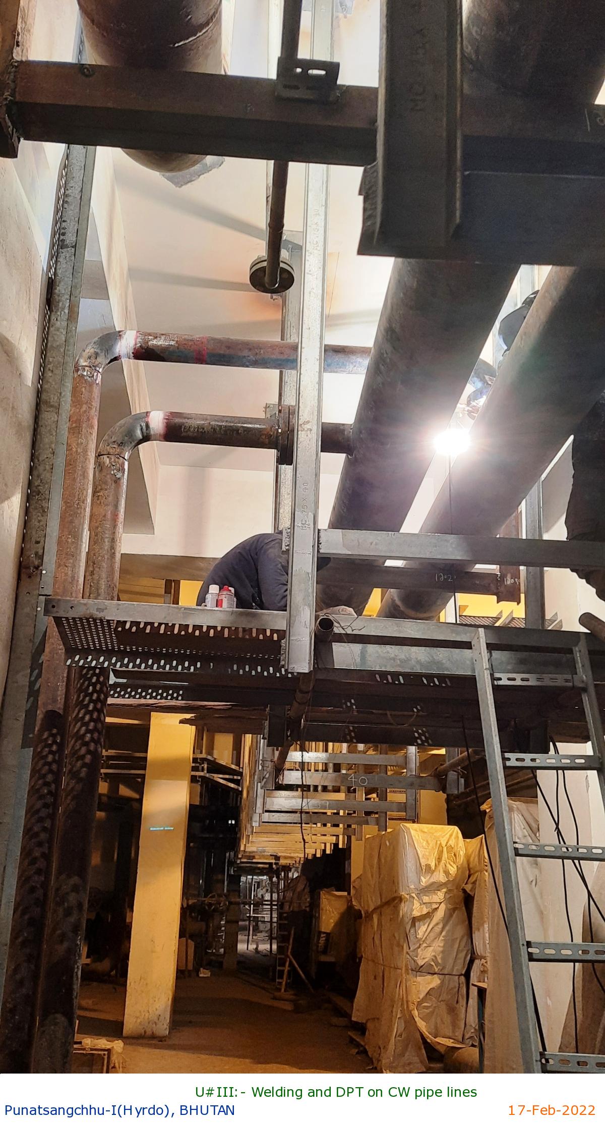
U#III:- Welding and DPT on CW pipe lines
|
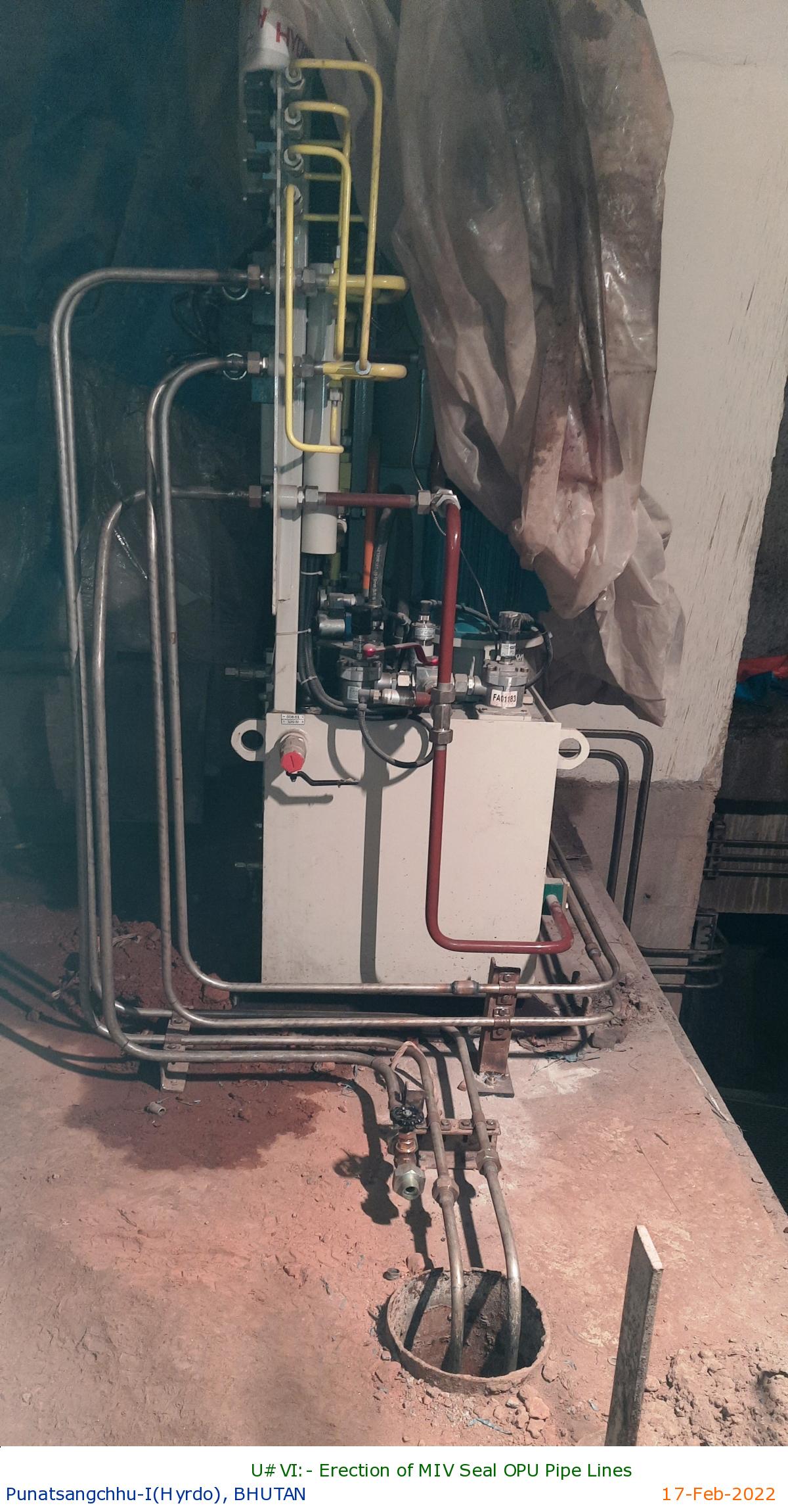
U#VI:- Erection of MIV Seal OPU Pipe Lines
|
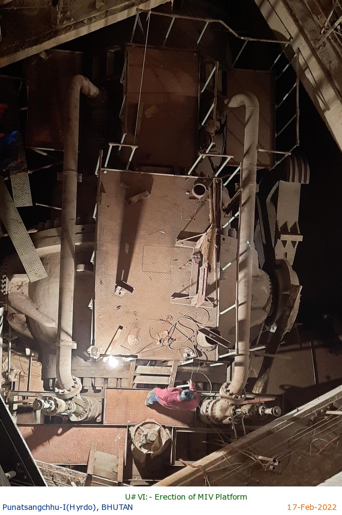
U#VI:- Erection of MIV Platform
|
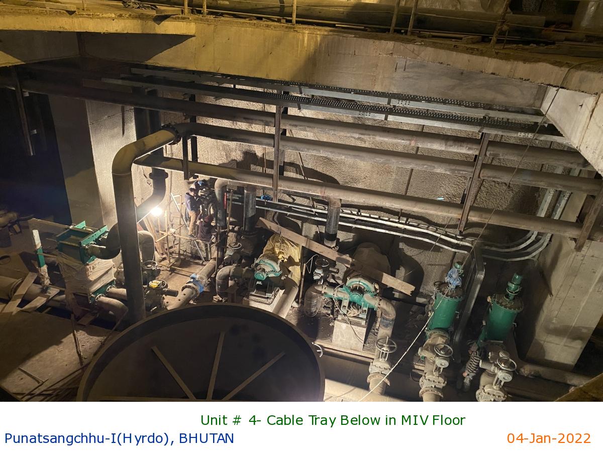
Unit # 4- Cable Tray Below in MIV Floor
|
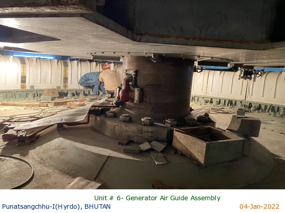
Unit # 6- Generator Air Guide Assembly
|
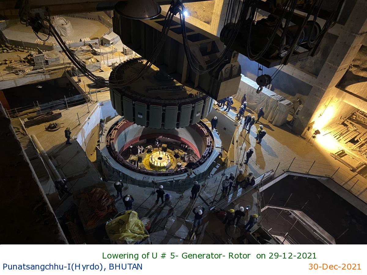
Lowering of U # 5- Generator- Rotor on 29-12-2021
|
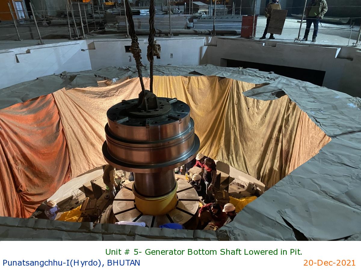
Unit # 5- Generator Bottom Shaft Lowered in Pit.
|
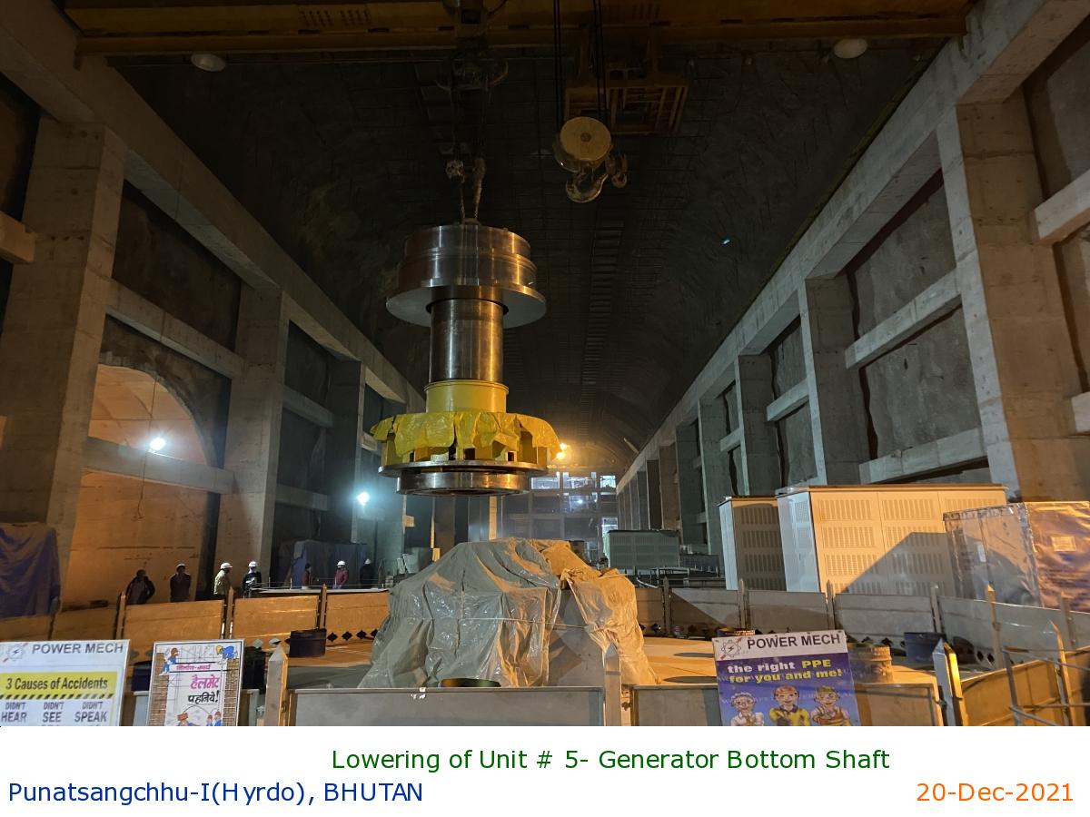
Lowering of Unit # 5- Generator Bottom Shaft
|
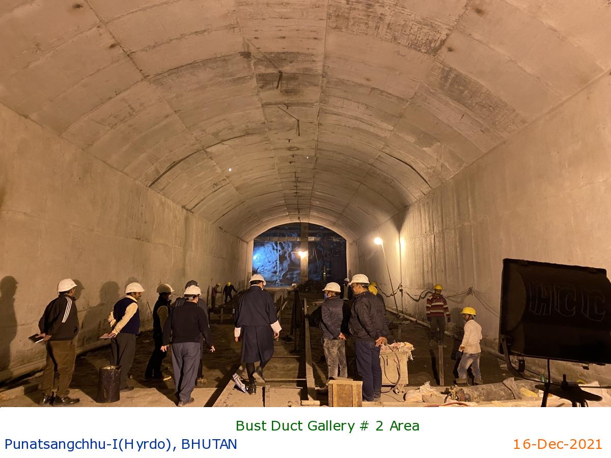
Bust Duct Gallery # 2 Area
|
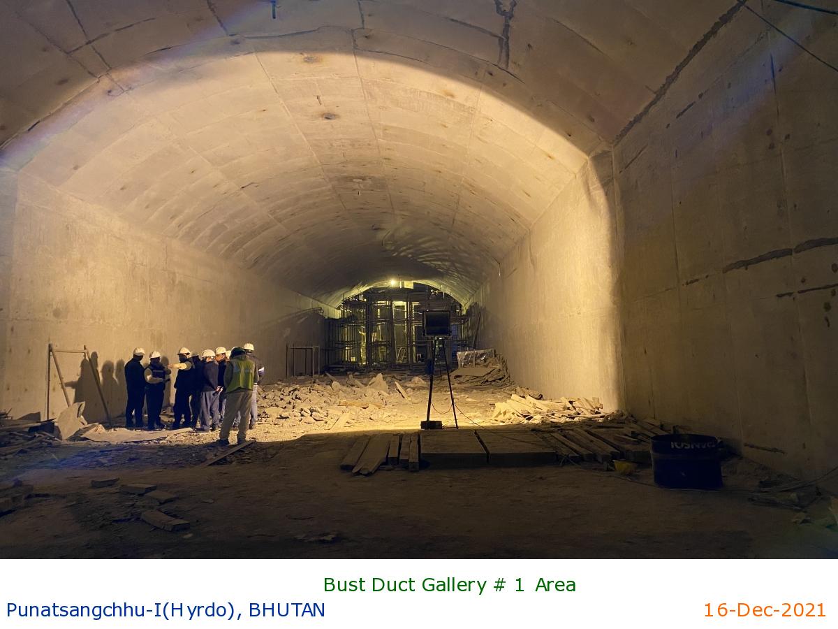
Bust Duct Gallery # 1 Area
|
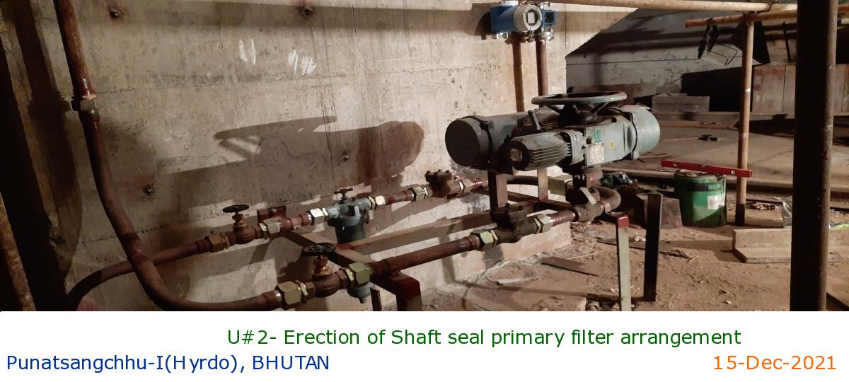
U#2- Erection of Shaft seal primary filter arrangement
|
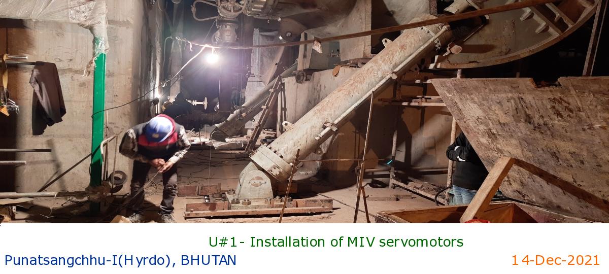
U#1- Installation of MIV servomotors
|
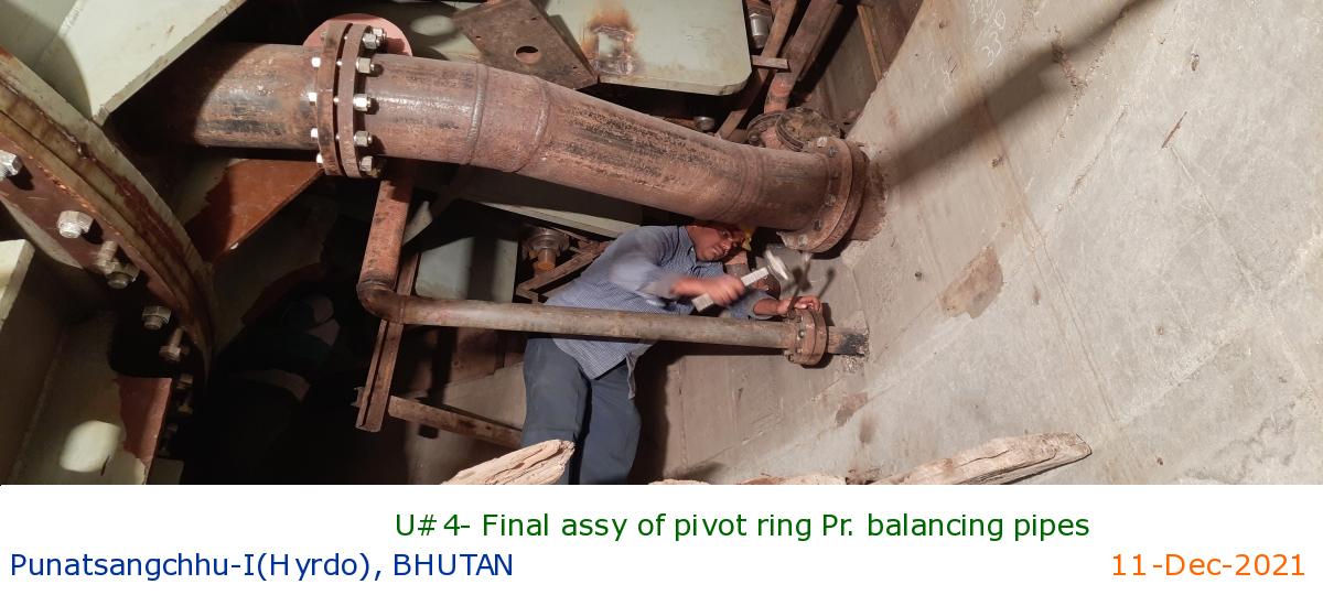
U#4- Final assy of pivot ring Pr. balancing pipes
|
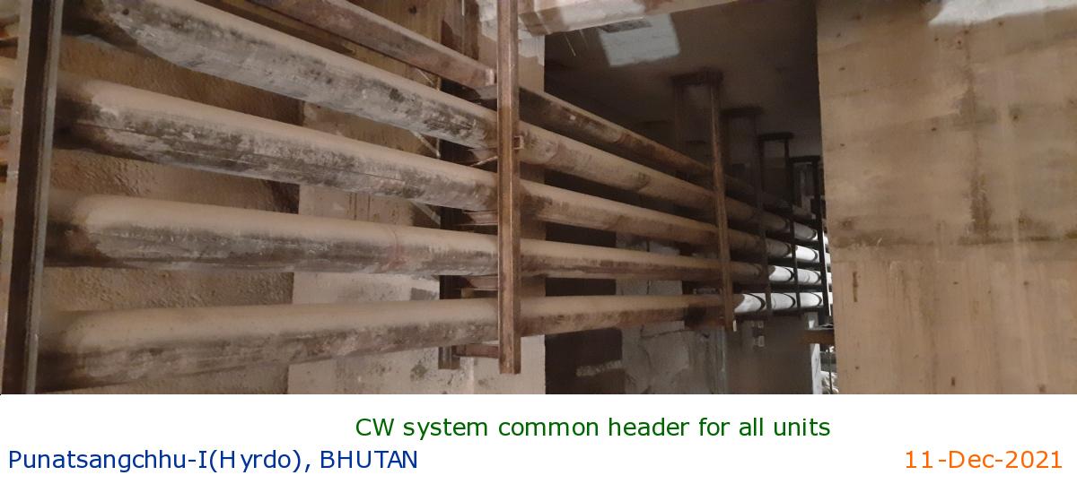
CW system common header for all units
|
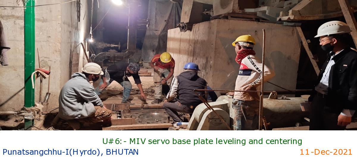
U#6:- MIV servo base plate leveling and centering
|
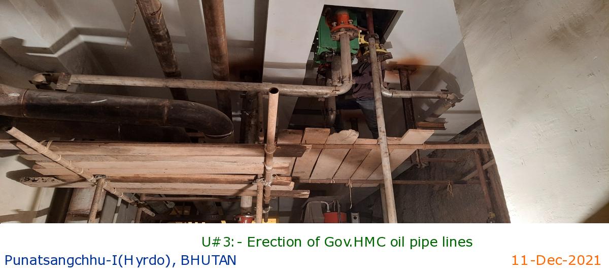
U#3:- Erection of Gov.HMC oil pipe lines
|
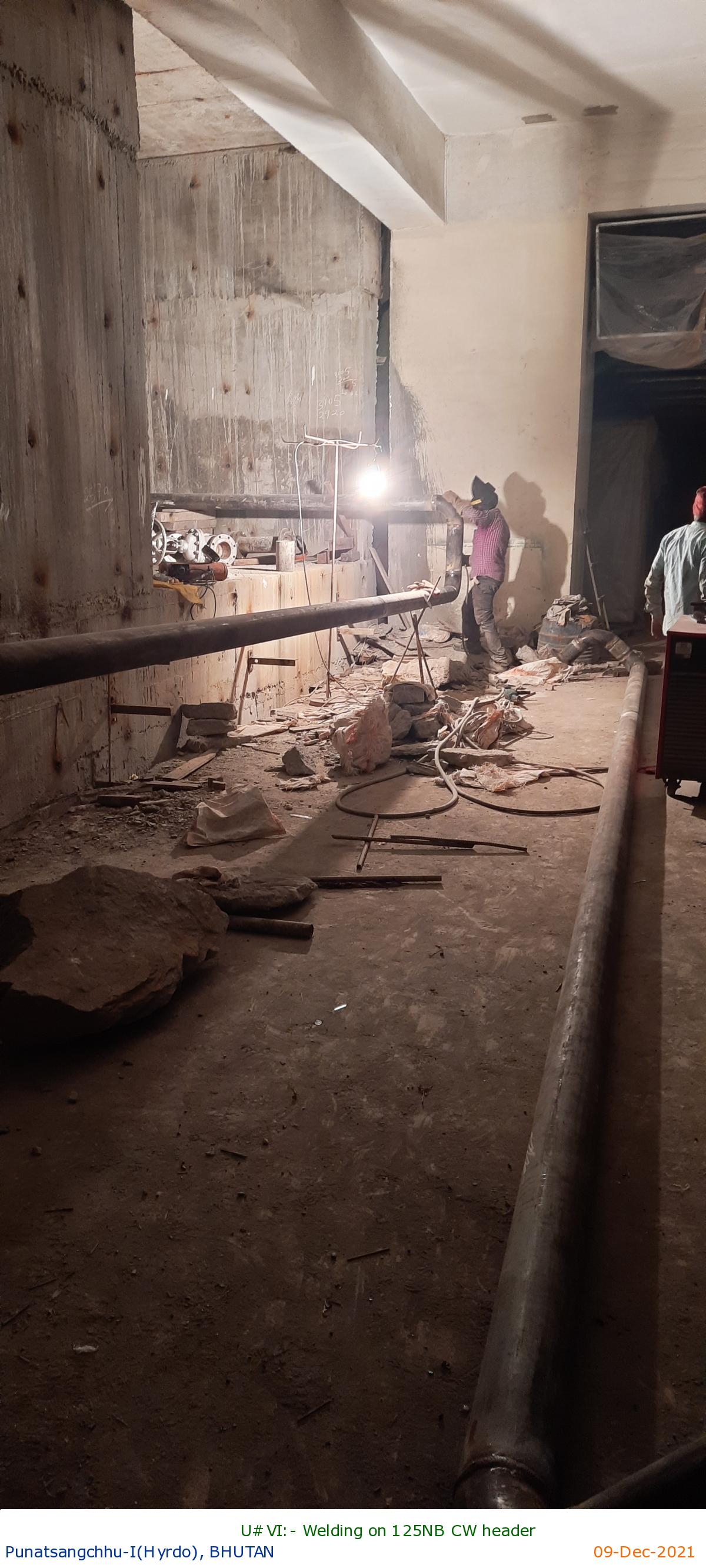
U#VI:- Welding on 125NB CW header
|
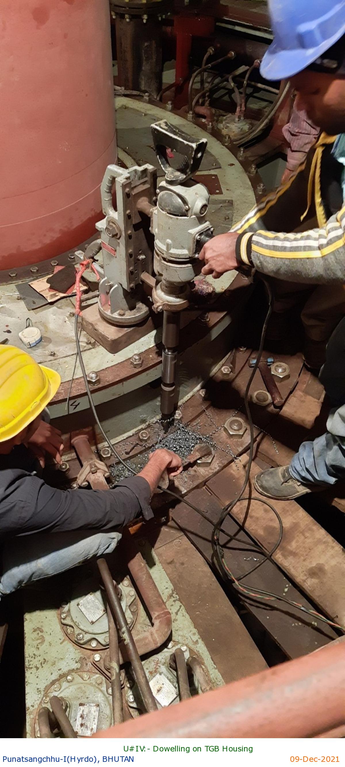
U#IV:- Dowelling on TGB Housing
|
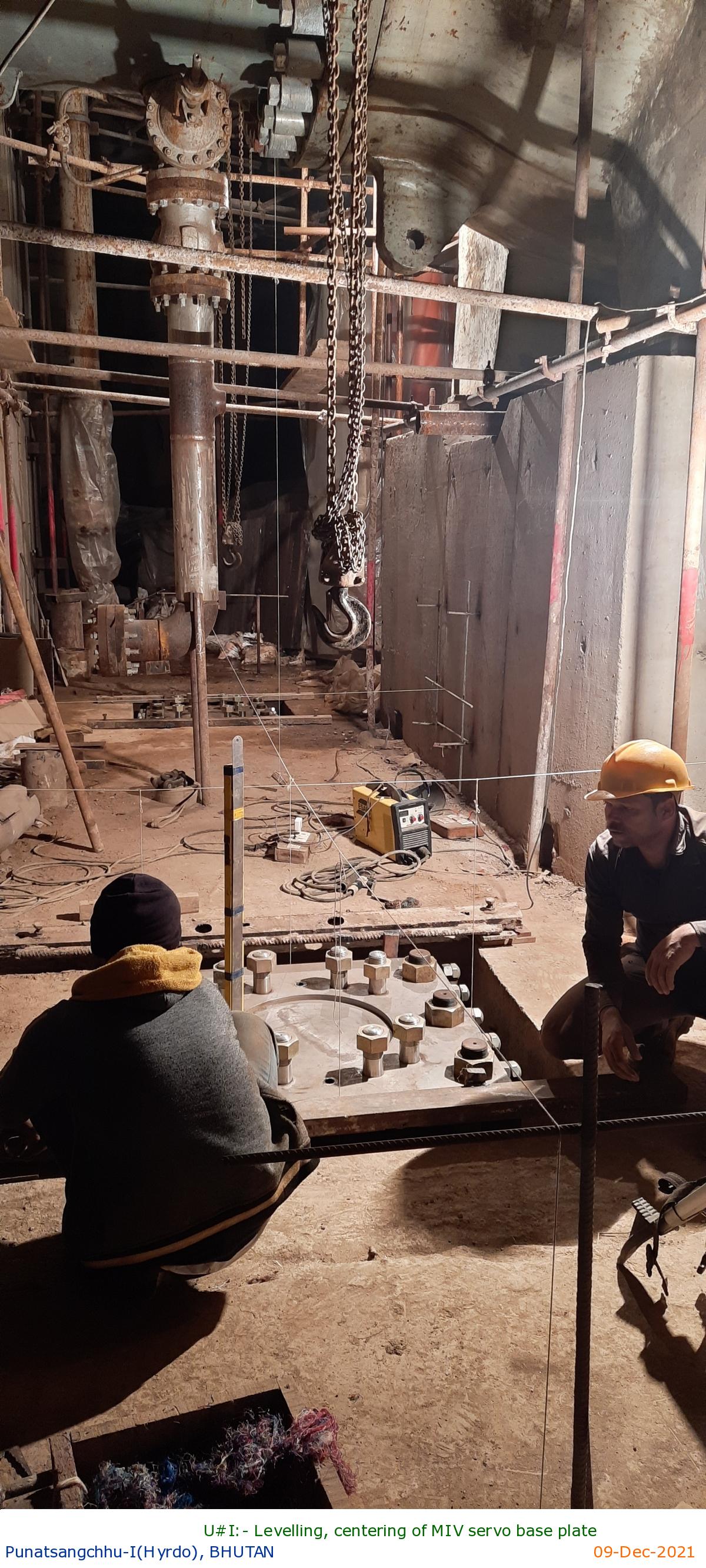
U#I:- Levelling, centering of MIV servo base plate
|
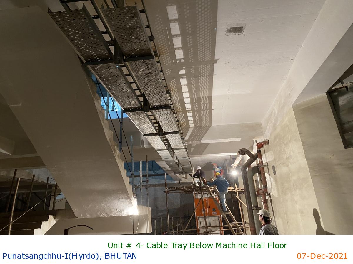
Unit # 4- Cable Tray Below Machine Hall Floor
|
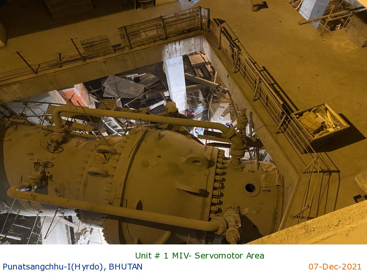
Unit # 1 MIV- Servomotor Area
|
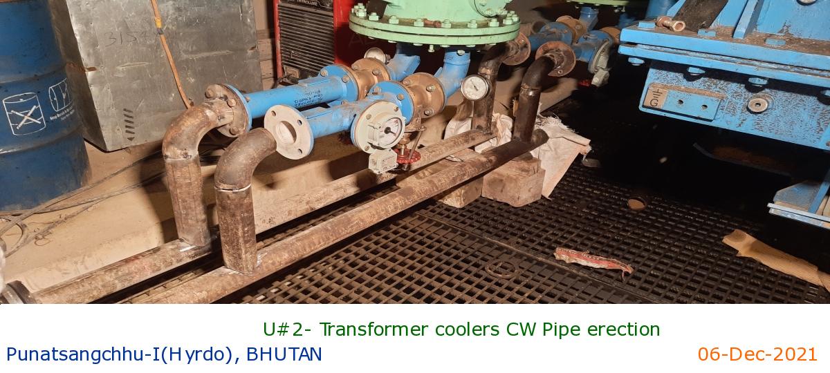
U#2- Transformer coolers CW Pipe erection
|
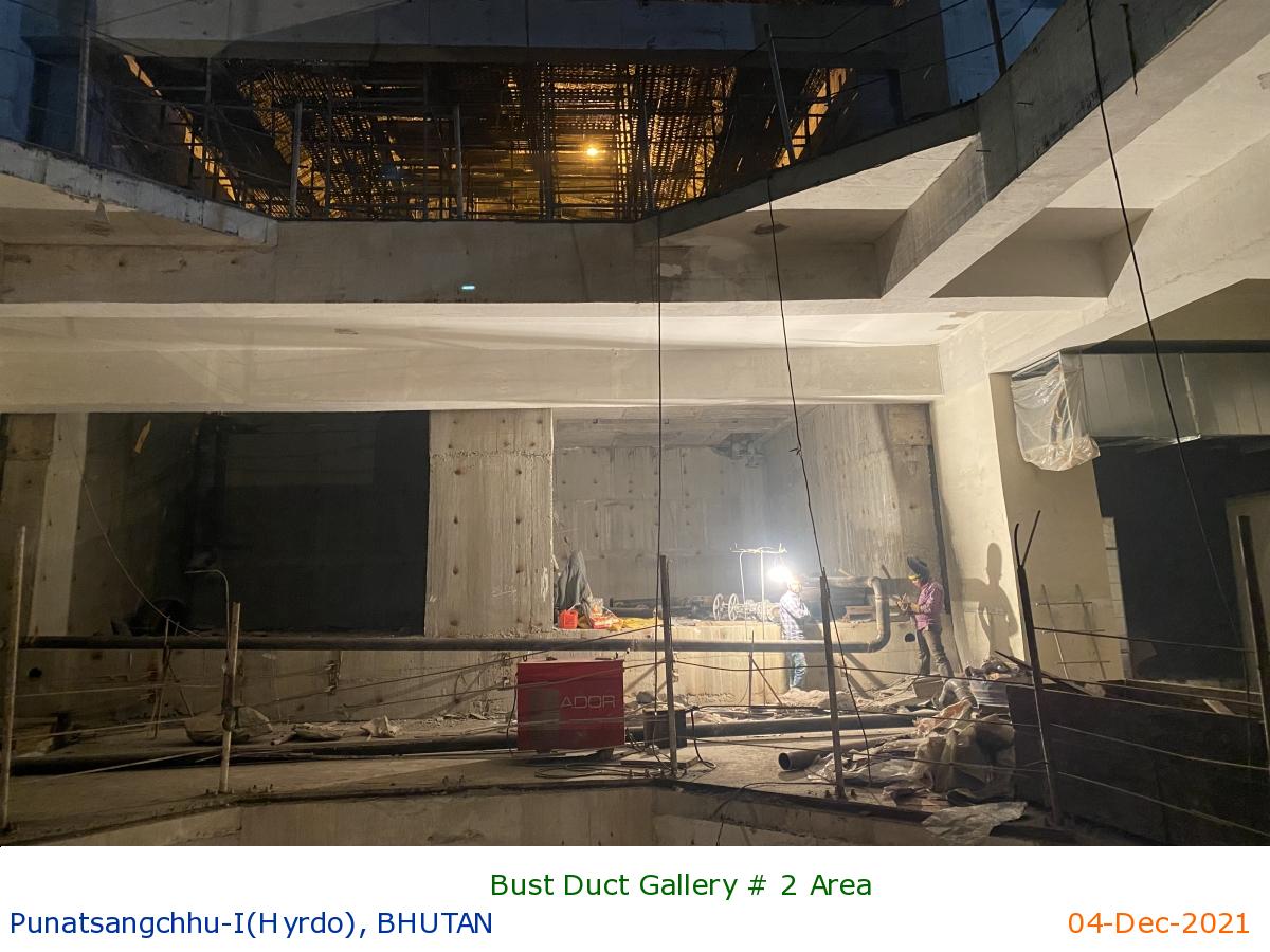
Bust Duct Gallery # 2 Area
|
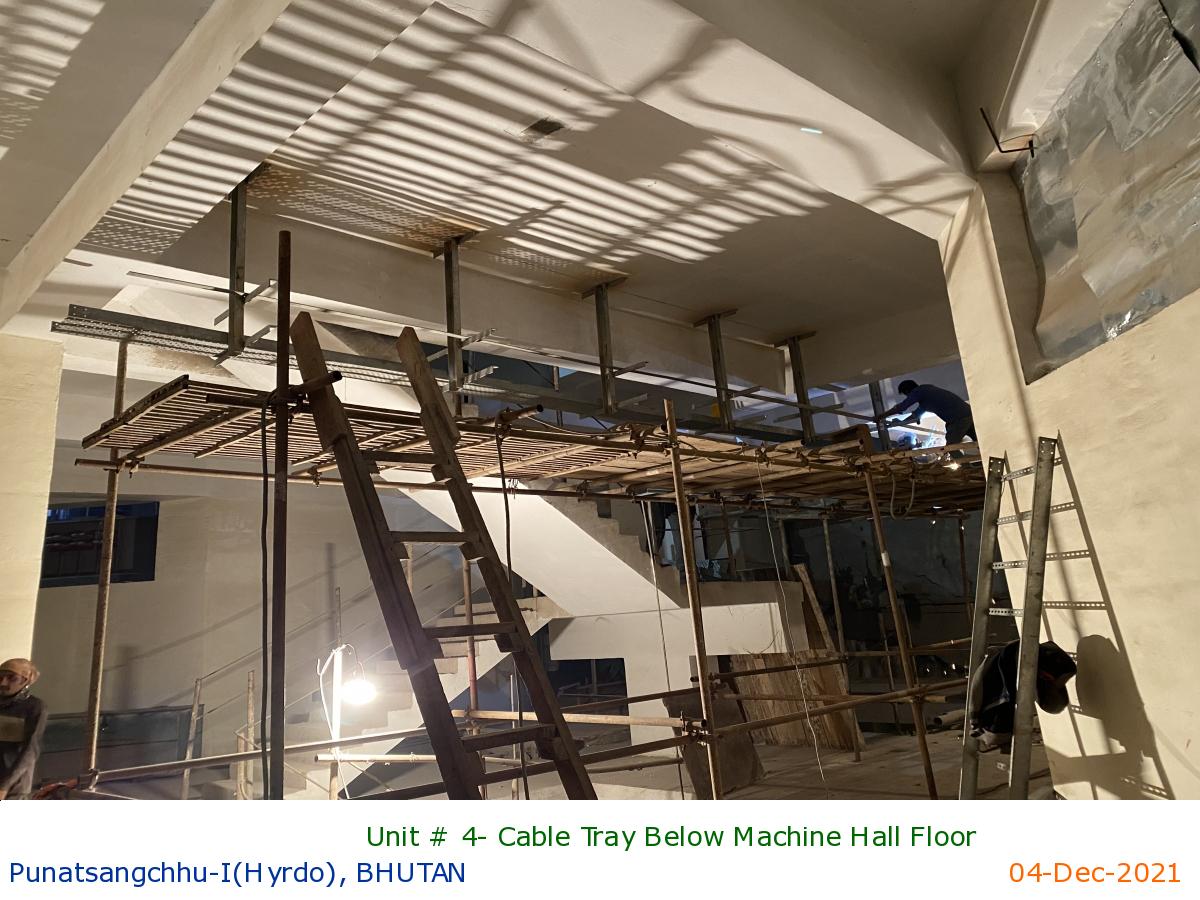
Unit # 4- Cable Tray Below Machine Hall Floor
|
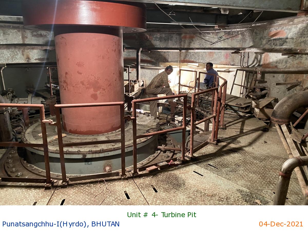
Unit # 4- Turbine Pit
|
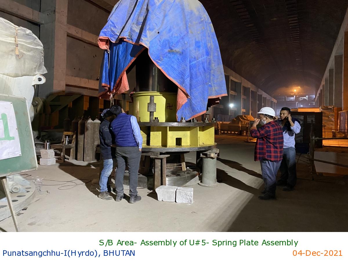
S/B Area- Assembly of U#5- Spring Plate Assembly
|
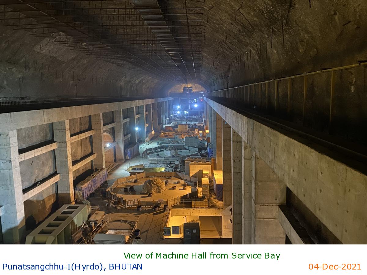
View of Machine Hall from Service Bay
|
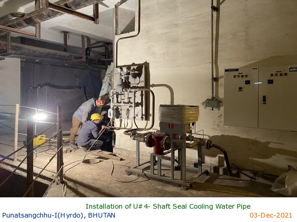
Installation of U#4- Shaft Seal Cooling Water Pipe
|
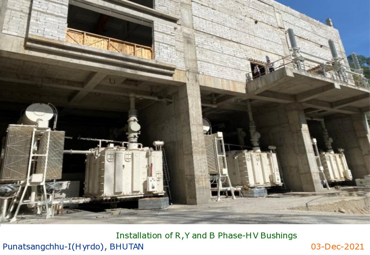
Installation of R,Y and B Phase-HV Bushings
|
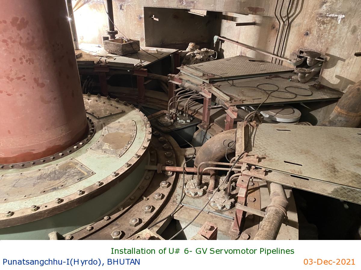
Installation of U# 6- GV Servomotor Pipelines
|
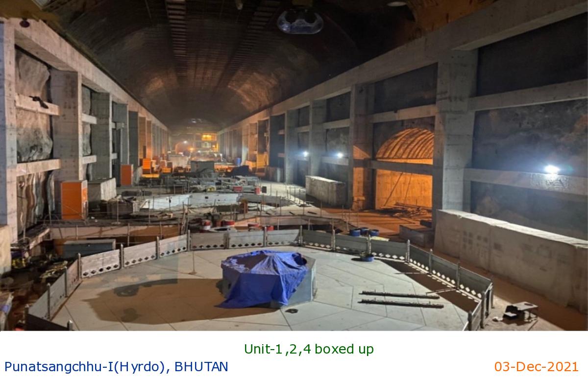
Unit-1,2,4 boxed up
|
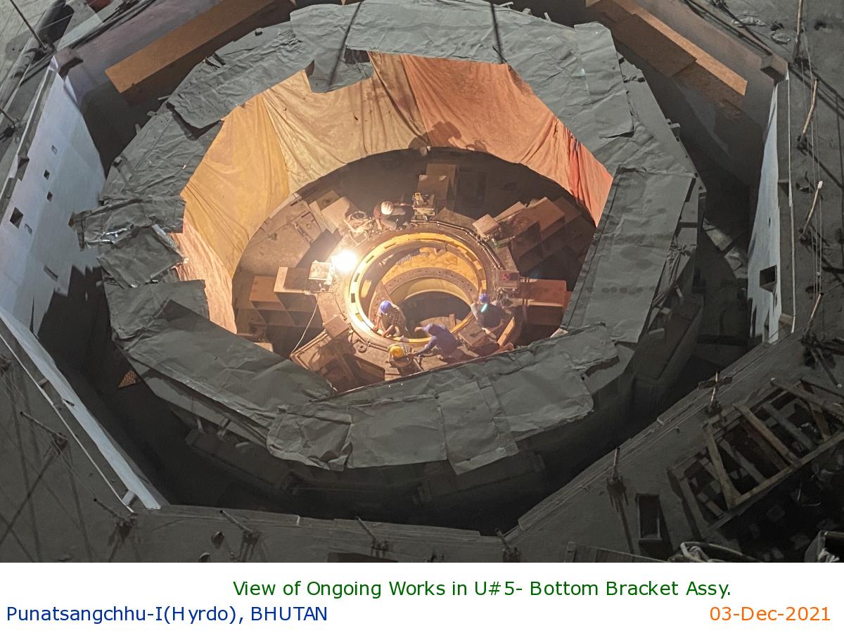
View of Ongoing Works in U#5- Bottom Bracket Assy.
|
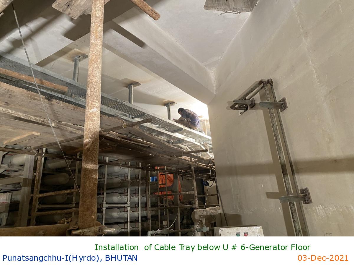
Installation of Cable Tray below U # 6-Generator Floor
|
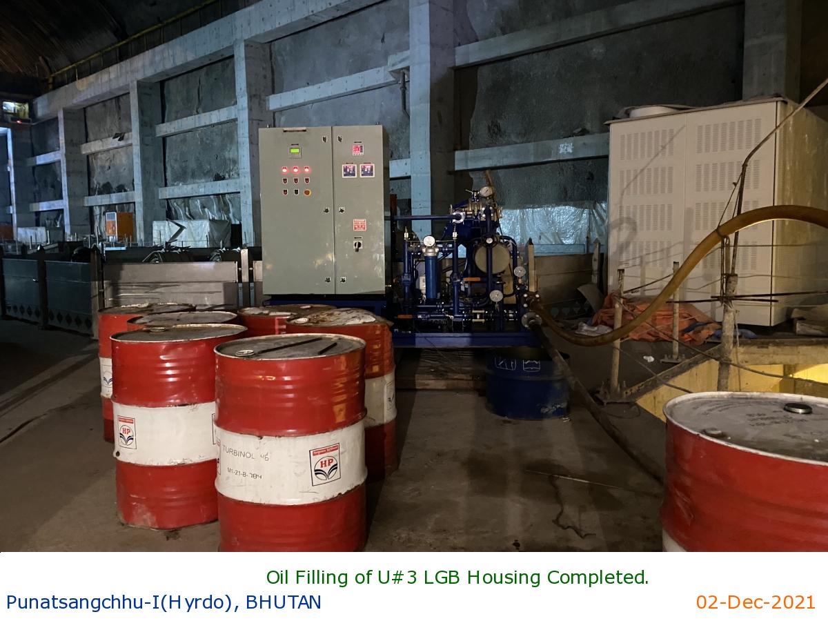
Oil Filling of U#3 LGB Housing Completed.
|
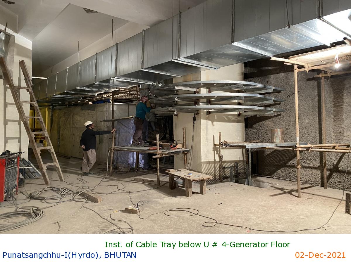
Inst. of Cable Tray below U # 4-Generator Floor
|
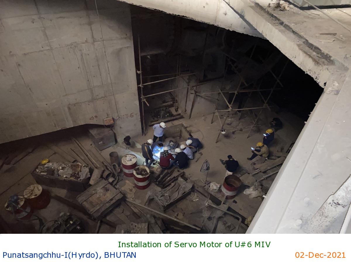
Installation of Servo Motor of U#6 MIV
|
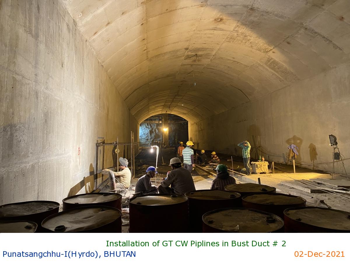
Installation of GT CW Piplines in Bust Duct # 2
|
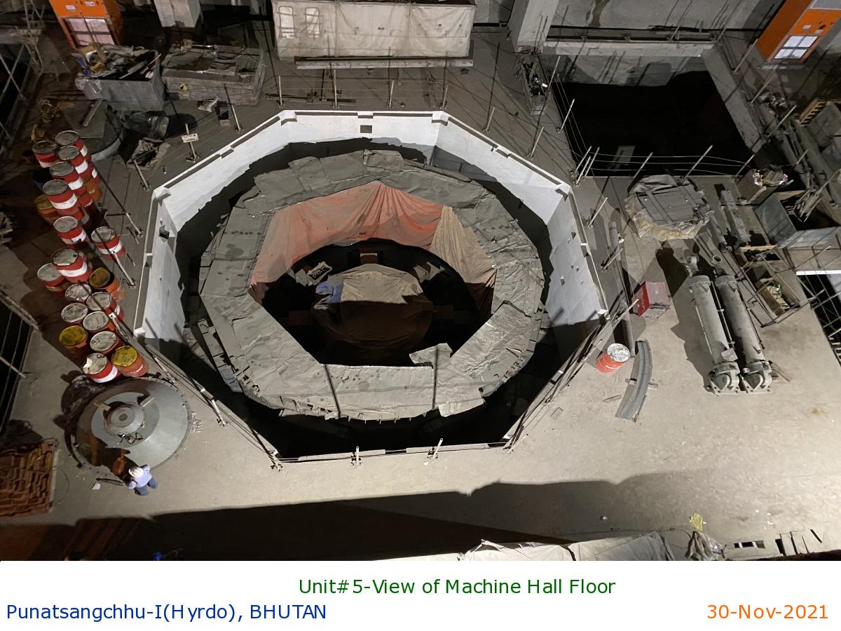
Unit#5-View of Machine Hall Floor
|
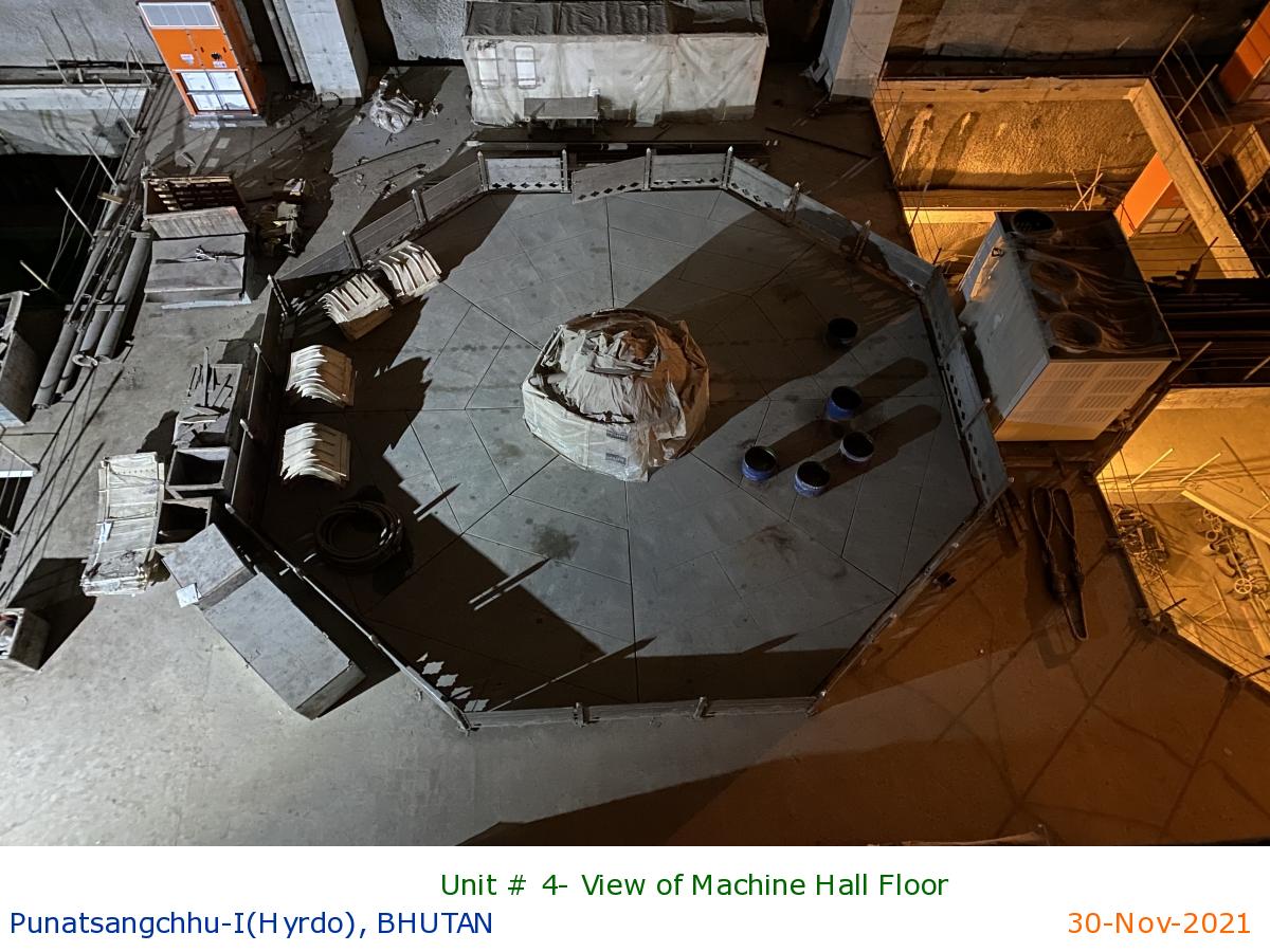
Unit # 4- View of Machine Hall Floor
|
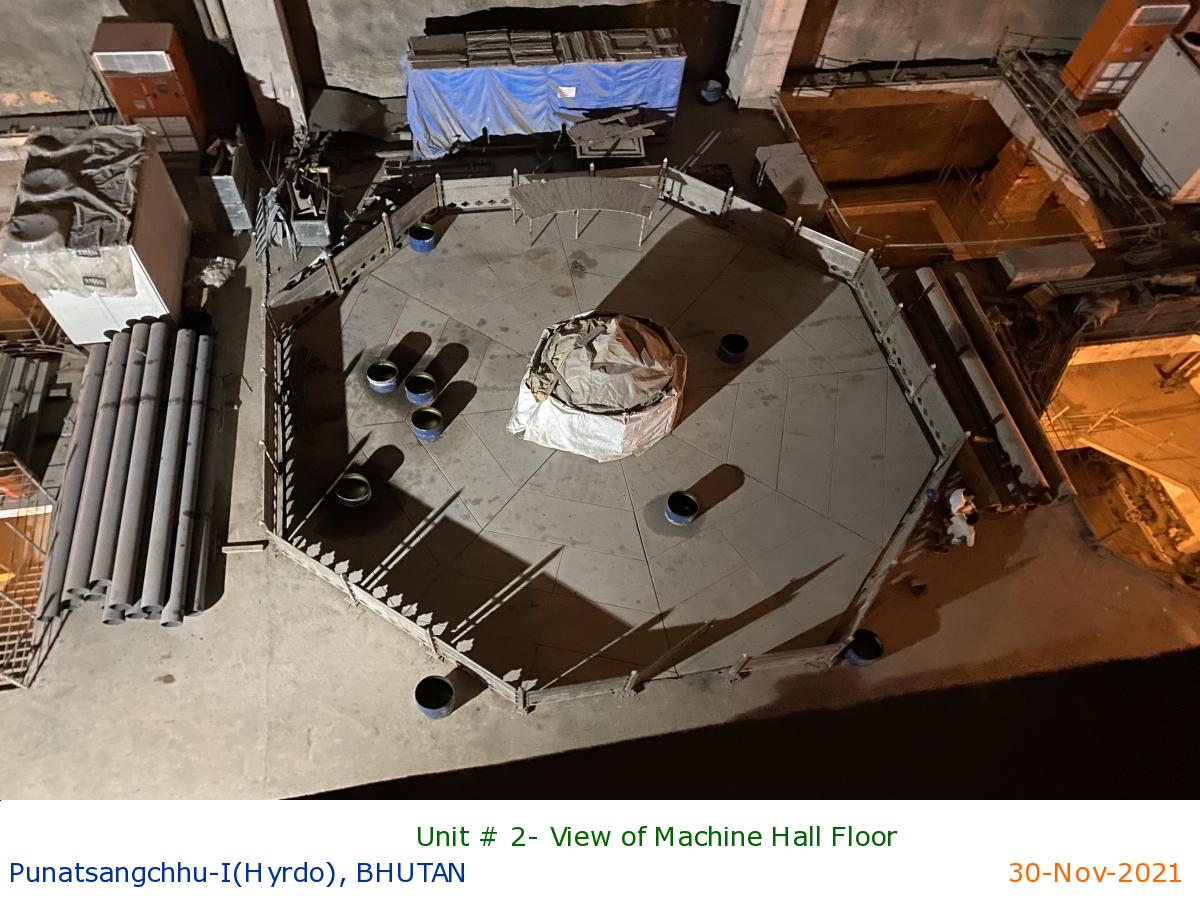
Unit # 2- View of Machine Hall Floor
|
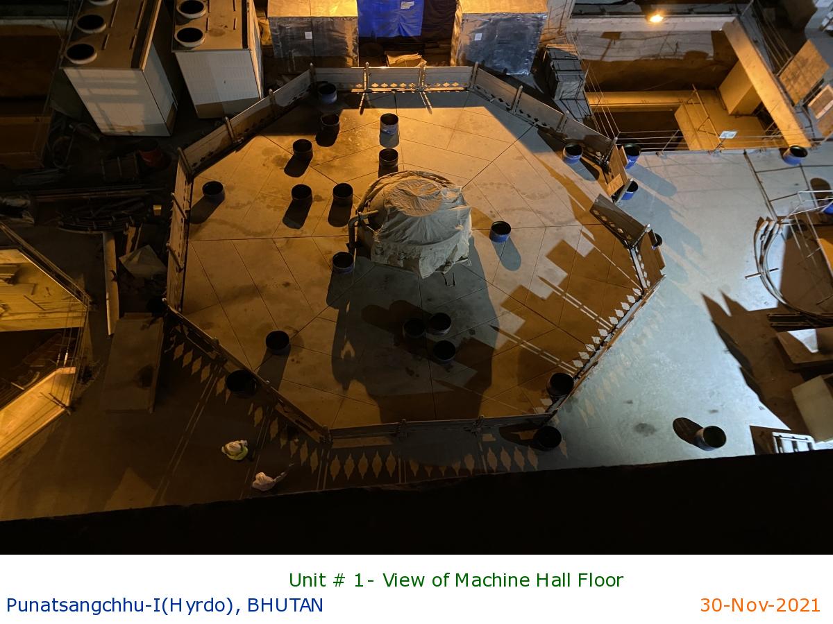
Unit # 1- View of Machine Hall Floor
|
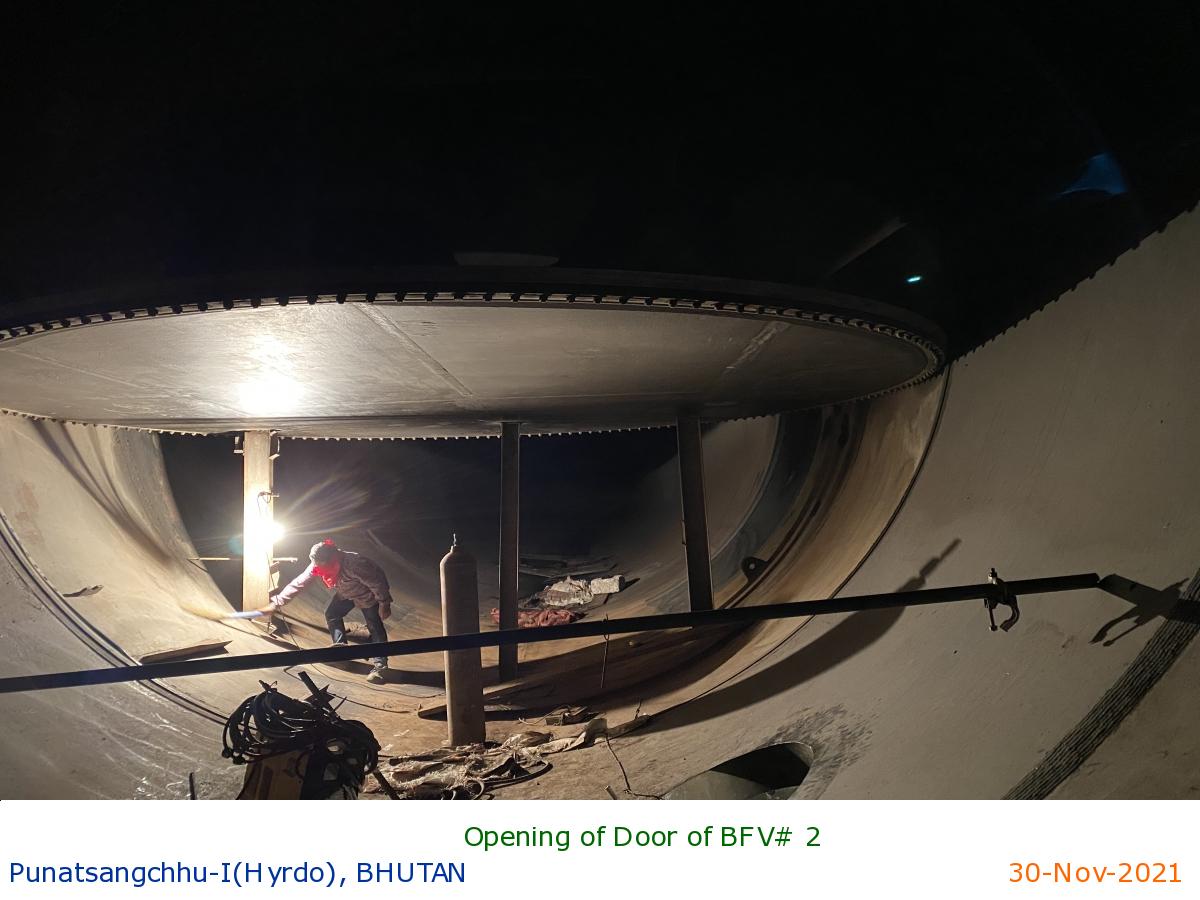
Opening of Door of BFV# 2
|
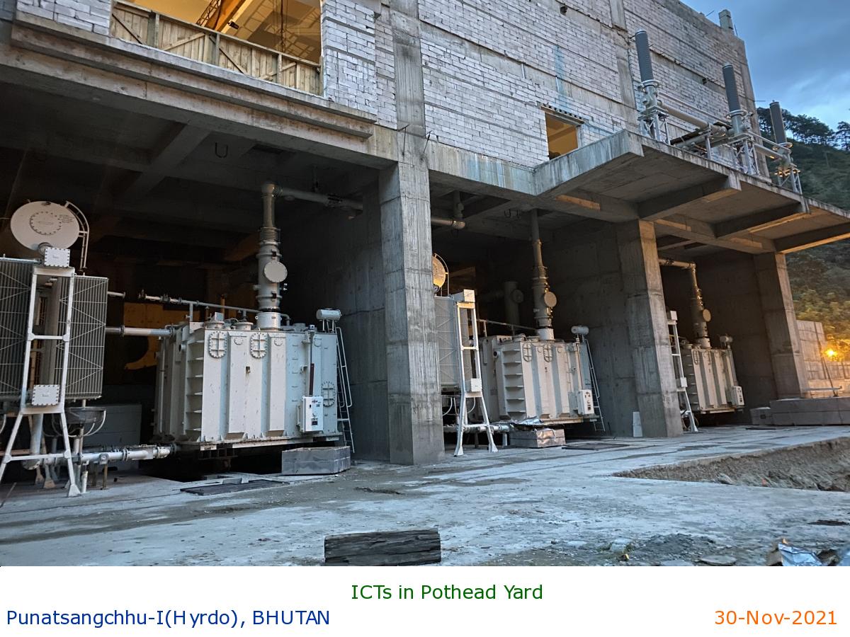
ICTs in Pothead Yard
|
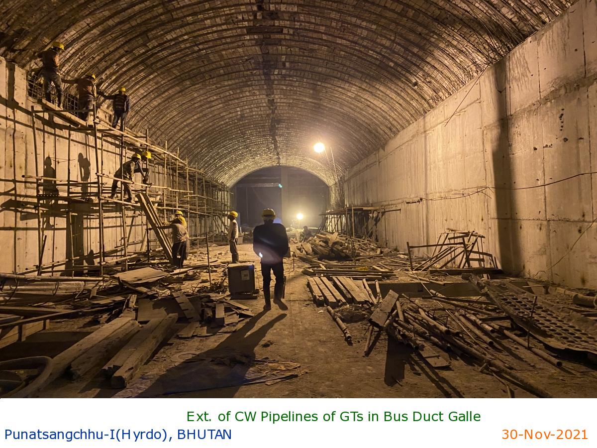
Ext. of CW Pipelines of GTs in Bus Duct Galle
|
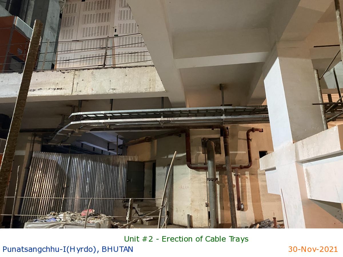
Unit #2 - Erection of Cable Trays
|
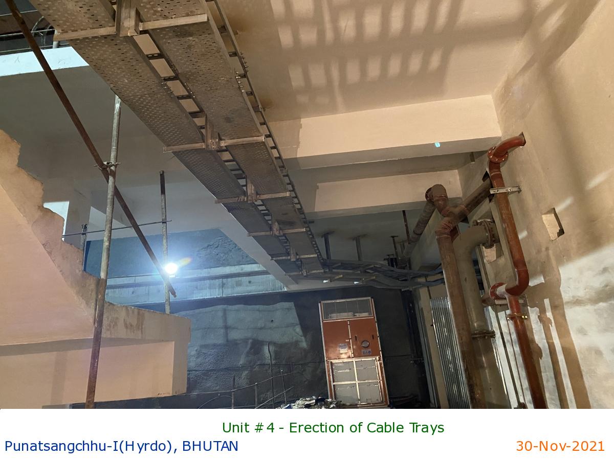
Unit #4 - Erection of Cable Trays
|
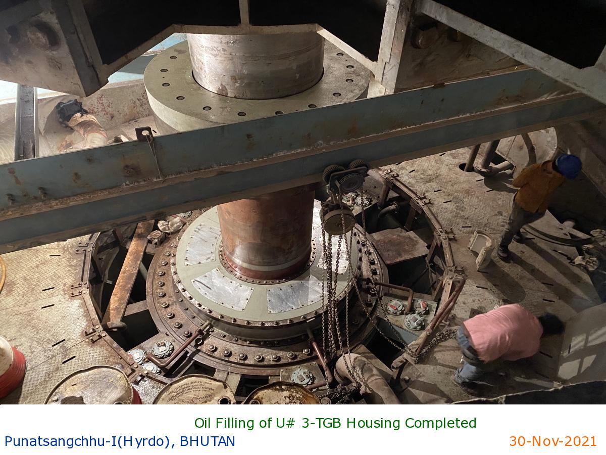
Oil Filling of U# 3-TGB Housing Completed
|
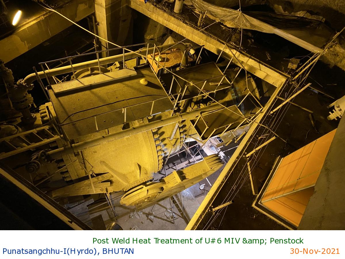
Post Weld Heat Treatment of U#6 MIV & Penstock
|
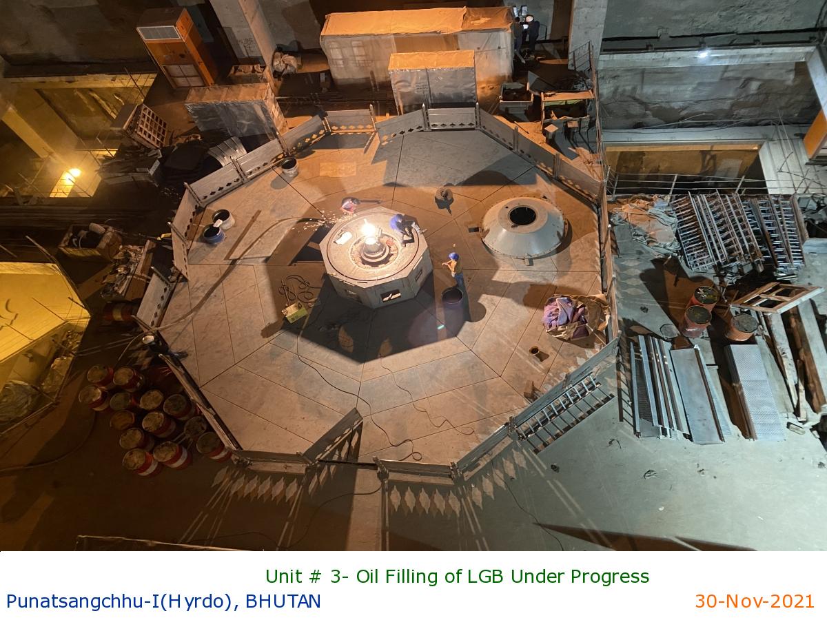
Unit # 3- Oil Filling of LGB Under Progress
|
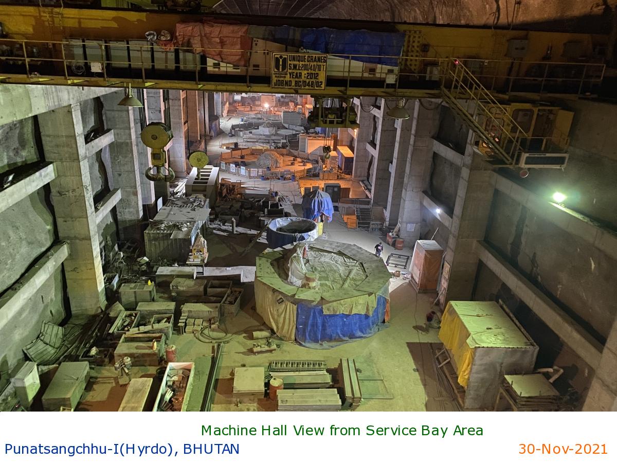
Machine Hall View from Service Bay Area
|